EN
EN English
 中文简体
中文简体 русский
 Deutsch
 日本語
日本語 한국어
한국어

A sensor magnet is the decisive element that converts mechanical motion into an interpretable magnetic field signal, directly determining the accuracy, reliability, and longevity of contactless position, speed, and angle measurement systems. Without a precisely engineered permanent magnet, even the most sophisticated magnetic sensing chip cannot deliver trustworthy data. Today, breakthroughs in rare-earth material formulations, geometric optimization, and temperature-stable coatings are pushing sensor magnet performance into new territory, enabling sub-micron linear resolution and angular accuracy below 0.1 degrees. This article examines the material science, design methodologies, and application landscapes that make the sensor magnet a cornerstone of modern electrification and automation.
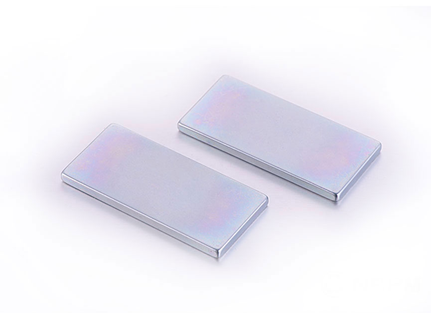
Explore Key Applications of Magnetic Materials
1. The Expanding Role of Sensor Magnets in a Data-Driven World
The global magnetic sensor market, directly fueled by demand for high-performance sensor magnet components, reached a valuation of USD 5.8 billion in 2023 and is projected to climb to USD 9.3 billion by 2030 at a compound annual growth rate of 7.2 percent, according to a 2024 report by Grand View Research. This growth stems from three unstoppable trends: vehicle electrification, factory automation, and the proliferation of connected devices. In every case, the sensor magnet sits at the physical interface between the moving part and the electronic control unit.
A sensor magnet works by generating a defined magnetic field that is detected by a Hall-effect, AMR (anisotropic magnetoresistive), GMR (giant magnetoresistive), or TMR (tunnel magnetoresistive) sensor element. As the magnet moves relative to the sensor, the field vector changes, translating position or rotation into a measurable electrical signal. This principle underpins everything from electronic power steering torque sensors to collaborative robot joint encoders.
1.1 Automotive Electrification Demands Zero-Failure Sensor Magnets
Modern vehicles contain between 60 and 120 magnetic sensors, and each requires a custom sensor magnet. Key applications include crankshaft position sensing, wheel speed detection for ABS and stability control, throttle position monitoring, and rotor position feedback in traction motors. In electric power steering systems, a diametrically magnetized ring magnet paired with a Hall array delivers torque angle measurement with a resolution better than 0.05 degrees, directly influencing steering feel and safety. A single-point failure in a sensor magnet due to demagnetization at 180 degrees Celsius or mechanical fracture can lead to loss of critical vehicle functions, driving stringent material qualification standards.
1.2 Industrial Automation Relies on Robust Magnetic Feedback
Factory floors present extreme conditions: coolant splash, metallic dust, vibration, and wide temperature swings from minus 40 to plus 120 degrees Celsius. Sensor magnet assemblies in linear encoders and rotary position sensors must maintain magnetic flux stability within 1 percent over a 10-year service life. Collaborative robots use compact multi-pole ring magnets to achieve joint position accuracy of plus minus 0.01 millimeters, enabling safe human-robot interaction. According to data from the International Federation of Robotics, global industrial robot installations exceeded 550,000 units in 2023, each incorporating multiple sensor magnet based feedback loops.
1.3 IoT and Consumer Devices Miniaturize Sensor Magnet Architectures
Smart water meters, wearable health monitors, and drone gimbals all employ miniature sensor magnet components often measuring less than 3 millimeters in diameter. In these applications, the challenge is to maximize magnetic energy density within a severely constrained volume while resisting corrosion from sweat or environmental moisture. A 2023 study published in the IEEE Sensors Journal demonstrated that a 2.5 mm diameter samarium-cobalt sensor magnet retained 98 percent of its room-temperature flux after 2,000 hours at 85 degrees Celsius and 85 percent relative humidity, validating its suitability for long-life IoT deployments.
2. Permanent Magnet Material Selection Shapes Sensor Performance
The magnetic, thermal, and mechanical properties of a sensor magnet are defined at the material level. Engineers must balance remanence, coercivity, temperature coefficients, and cost. The four dominant material families are neodymium-iron-boron (NdFeB), samarium-cobalt (SmCo), hard ferrite, and alnico. Each offers a distinct trade-off profile. The table below compares critical parameters based on industry datasheet averages and data from the MMPA (Magnetic Materials Producers Association) Standard No. 0100.
| Material Grade | Remanence Br (kG) | Coercivity HcJ (kOe) | Max Operating Temp (°C) | Temperature Coefficient of Br (%/°C) | Relative Cost |
|---|---|---|---|---|---|
| NdFeB N48H | 13.8 | 17 | 120 | -0.11 | Medium |
| SmCo Sm2Co17 26H | 10.5 | 18 | 350 | -0.035 | High |
| Hard Ferrite Y30 | 3.8 | 3.2 | 250 | -0.20 | Low |
| Alnico 5 | 12.5 | 0.65 | 540 | -0.02 | Medium |
Table 1: Comparison of key magnetic and thermal properties for common sensor magnet material families. Data represents typical commercial grade values.
NdFeB magnets deliver the highest energy density, making them ideal for miniaturized sensor magnet designs where space is at a premium. However, their relatively steep temperature coefficient of remanence means that a 100 degree Celsius temperature rise can reduce the magnetic flux by roughly 11 percent, which must be compensated through sensor calibration or material grade selection. Samarium-cobalt offers exceptional thermal stability and corrosion resistance without the need for protective coatings, but at a significantly higher raw material cost. Hard ferrite sensor magnet solutions dominate cost-sensitive applications such as household appliance speed sensors, where the lower flux can be offset by larger magnet volume or more sensitive sensing elements. Alnico, despite its low coercivity, finds niche use in high-temperature environments above 400 degrees Celsius, such as turbine speed probes, because its remanence remains nearly constant.
3. Design Geometry and Magnetization Patterns Dictate Signal Quality
The physical shape and magnetization orientation of a sensor magnet are not arbitrary; they are engineered to produce a specific magnetic field distribution that maximizes the linear range and minimizes harmonic distortion in the sensor output. The following geometric factors directly impact sensing accuracy.
- Diametrically magnetized cylinders and rings: Used extensively in angular position sensing, these sensor magnet configurations generate a rotating dipole field. The field uniformity across the rotation angle determines the achievable accuracy. A 2022 simulation study in the Journal of Magnetism and Magnetic Materials showed that a ring with an outer-to-inner diameter ratio of 1.6 and a length-to-diameter ratio of 0.8 minimized the total harmonic distortion to below 0.3 percent over 360 degrees.
- Axially magnetized discs and blocks: For linear position sensing, an axially magnetized sensor magnet creates a field that decays predictably with distance. The linear sensing range is typically limited to about 60 percent of the magnet's face dimension. Beyond this range, the field gradient becomes too shallow to resolve small displacements accurately.
- Multi-pole magnetized strips and rings: Incremental encoders rely on alternating north-south poles on a magnetic strip. The pole pitch, commonly ranging from 1 millimeter to 5 millimeters, defines the base resolution. A finer pole pitch improves resolution but demands a smaller air gap between the sensor magnet surface and the sensing element, increasing sensitivity to runout and mechanical tolerances.
- Trapezoidal and tapered profiles: To linearize the output of a Hall sensor over a longer stroke, some sensor magnet designs employ a varying cross-section. As the magnet moves, the changing amount of magnetic material facing the sensor produces a nearly linear voltage-displacement relationship without complex signal processing.
Temperature compensation is another critical design lever. Because both the sensor magnet remanence and the Hall sensor sensitivity drift with temperature, system designers often select a magnet material whose temperature coefficient partially cancels the sensor's own drift. For example, a GaAs Hall element exhibits a sensitivity temperature coefficient of approximately minus 0.06 percent per degree Celsius. Pairing it with a samarium-cobalt sensor magnet that has a remanence coefficient of minus 0.035 percent per degree Celsius leaves a net drift of only minus 0.025 percent per degree Celsius, reducing the need for external compensation circuits.
4. Protecting Sensor Magnets from Environmental Degradation
A sensor magnet exposed to moisture, salt spray, or aggressive chemicals can suffer rapid corrosion, leading to magnetic flux loss and particulate contamination that interferes with the sensor gap. NdFeB magnets are particularly vulnerable due to their high iron content. Without protection, a bare NdFeB sensor magnet can lose 5 percent of its weight to corrosion within 100 hours of salt spray testing per ASTM B117. The following protective strategies are industry standard.
- Multi-layer coatings: A typical high-reliability sensor magnet receives a nickel-copper-nickel electroplated layer, providing a total thickness between 10 and 25 microns. For automotive underhood environments, an additional epoxy topcoat of 15 to 30 microns is applied, achieving over 1,000 hours of salt spray resistance.
- Parylene conformal coating: For miniature medical or implantable sensor magnet applications, vapor-deposited Parylene C offers a pinhole-free, biocompatible barrier at thicknesses as low as 5 microns, ensuring hermetic-level protection without dimensional buildup.
- Overmolding and encapsulation: Insert molding the sensor magnet into a thermoplastic housing such as PPS or PA66 with glass fiber reinforcement simultaneously provides corrosion protection, mechanical mounting features, and precise alignment surfaces for the sensor IC.
- Material substitution: In subsea or chemical processing equipment, designers often bypass coating complexity entirely by selecting inherently corrosion-resistant SmCo for the sensor magnet, accepting a higher initial material cost to eliminate long-term degradation risk.
5. Comparing Sensing Technologies and Their Magnet Requirements
Different magnetic sensing principles impose distinct demands on the sensor magnet. Understanding these requirements prevents costly over-specification or performance shortfalls. The table below summarizes the relationship between sensor technology and the corresponding magnet characteristics.
| Sensor Technology | Typical Field Strength Requirement (mT) | Sensitive Field Component | Preferred Sensor Magnet Shape | Common Material Choice |
|---|---|---|---|---|
| Hall Effect | 20 – 100 | Perpendicular component | Axially magnetized disc | NdFeB or Ferrite |
| AMR | 5 – 20 | In-plane field direction | Diametrically magnetized ring | NdFeB or SmCo |
| GMR | 1 – 10 | In-plane field direction | Multi-pole strip | NdFeB or bonded NdFeB |
| TMR | 0.5 – 5 | In-plane field direction | Fine-pitch multi-pole ring | SmCo or high-grade NdFeB |
Table 2: Mapping between magnetic sensor technology and recommended sensor magnet characteristics for typical position sensing applications.
Hall-effect sensors, with their relatively high field requirement, work well with cost-effective ferrite sensor magnet solutions in applications where space allows. TMR sensors, the most sensitive, can operate with very small, low-profile magnets, enabling ultra-compact encoder designs. However, the low field strength requirement also makes TMR systems more susceptible to interference from stray magnetic fields generated by nearby motors or current-carrying conductors, necessitating careful shielding and sensor magnet placement.
Bonded magnets, produced by injection molding a mixture of magnetic powder and a polymer binder, deserve special mention. They allow complex shapes with tight tolerances to be molded directly, often integrating the sensor magnet with a shaft or gear in a single manufacturing step. While their magnetic performance is lower than that of fully dense sintered magnets, the design freedom they provide frequently outweighs the flux density penalty in high-volume automotive sensor applications.
6. Practical Design Checklist for Specifying a Sensor Magnet
Translating system requirements into a robust sensor magnet specification involves a structured evaluation across multiple domains. The following ordered checklist helps engineering teams avoid common pitfalls.
- Define the sensing air gap and mechanical envelope: Measure the maximum and minimum distance between the sensor magnet face and the sensing element, accounting for all assembly tolerances, thermal expansion, and vibration-induced displacement.
- Determine the required magnetic flux density at the sensor: Use finite element analysis or analytical models to confirm that the chosen magnet grade and geometry deliver at least 120 percent of the sensor's minimum operating field across the entire temperature range.
- Select the magnet material based on temperature stability: Calculate the worst-case flux variation from minus 40 to the maximum operating temperature. If the variation exceeds the sensor's allowable input range, switch to a sensor magnet material with a lower temperature coefficient.
- Specify the magnetization pattern and tolerance: For angular sensors, define the allowable angular deviation of the magnetization vector. A deviation of more than 0.5 degrees can cause measurable angle error in high-precision systems.
- Validate mechanical retention and corrosion protection: Ensure the sensor magnet is secured against rotational and axial forces using press-fit, adhesive bonding, or mechanical staking, and that the chosen coating withstands the intended chemical environment for the product's design life.
- Characterize the magnet-to-sensor alignment sensitivity: Perform a tolerance stack-up analysis to confirm that lateral and angular misalignment between the sensor magnet and the sensor IC does not shift the output beyond the calibrated range.
7. Frequently Asked Questions About Sensor Magnets
What is the difference between a sensor magnet and a general-purpose permanent magnet?
A sensor magnet is manufactured with tighter magnetic moment tolerances, often within plus minus 1.5 percent, and is designed to produce a precisely defined field pattern rather than maximum pull force. Its geometry, coating, and magnetization are optimized for a specific sensing IC, whereas a general-purpose magnet prioritizes brute holding force or cost.
How do I select the right sensor magnet grade for high-temperature applications above 150 degrees Celsius?
Choose a samarium-cobalt grade such as Sm2Co17 26H or a high-temperature NdFeB grade like N35AH. SmCo offers the best thermal stability up to 350 degrees Celsius, while high-temperature NdFeB grades can operate up to 230 degrees Celsius if the load line is sufficiently high to prevent irreversible demagnetization. Always verify the sensor magnet permeance coefficient under actual operating conditions.
Can a sensor magnet lose its magnetism over time?
Yes. All permanent magnets experience some long-term flux loss due to structural relaxation, oxidation, or external demagnetizing fields. A well-designed sensor magnet made from modern rare-earth materials typically exhibits less than 1 percent flux loss over 10 years when operated within its rated temperature and protected from corrosion. Accelerated aging tests at elevated temperatures are used to validate lifetime stability.
What are the most common shapes for sensor magnets, and why?
The most prevalent shapes are discs, rings, blocks, and arcs. Discs and rings dominate angular sensing because they produce a symmetric dipole field. Blocks are used for linear position sensing where travel direction is along a single axis. Arc-shaped sensor magnet segments are employed in limited-angle rotary sensors, such as throttle position indicators, where full 360-degree rotation is not needed.
Is it possible to use the same sensor magnet for Hall and TMR sensors?
It is possible but not optimal. A sensor magnet sized to provide a strong field for a Hall sensor may saturate a sensitive TMR element, degrading linearity. Conversely, a magnet designed for TMR may not supply sufficient flux to reliably trigger a Hall latch. The best approach is to tailor the sensor magnet strength and air gap specifically for the chosen sensor technology.
8. Looking Ahead: The Future of Sensor Magnet Technology
The next generation of sensor magnet development is focused on three frontiers: grain boundary diffusion processes that enhance coercivity without heavy rare-earth elements, additive manufacturing of near-net-shape magnets with complex internal cooling channels, and the integration of magnet and sensor into monolithic system-in-package modules. Research published in 2024 by the European Magnetism Association indicates that grain boundary diffused NdFeB magnets can achieve a 30 percent increase in coercivity while reducing dysprosium content by 60 percent, directly lowering both cost and supply chain risk for high-volume sensor magnet production.
Simultaneously, the push toward functional safety in autonomous vehicles is mandating redundant sensing architectures. This translates into dual-channel magnetic encoders where two independent sensor magnet tracks are integrated into a single mechanical component, each read by a separate sensor die, ensuring that no single point of failure can disable the position feedback loop. According to the ISO 26262 ASIL D standard, such redundancy is non-negotiable for steering and braking systems.
From the depths of an offshore oil well to the sterile environment of a surgical robot, the humble sensor magnet continues to prove that precise, reliable motion sensing starts with meticulously engineered magnetic materials. As industries demand ever-finer resolution and longer maintenance-free lifetimes, investment in sensor magnet innovation will remain a high-return priority for component suppliers and system integrators alike.