EN
 English
 中文简体
 русский
 Deutsch
 日本語
 한국어


A Halbach array is a permanent-magnet assembly in which each magnet is rotated roughly 90 degrees relative to its neighbour, concentrating flux on one face and cancelling it on the other. No special material is required — standard sintered NdFeB segments do the job. If you searched for "hallbach array", you are looking at the same geometry; only the spelling differs.
The practical answer up front: for the same magnet volume, a well-built Halbach array puts more usable flux into an air gap than a conventional parallel-magnetized block, and it needs little or no back iron. The cost is paid in part count, orientation tolerance and assembly labour. A rotor built from four blocks in a conventional design may need 32 individually oriented segments to fill the same envelope in a Halbach version.
What follows is the rotation rule, the parameters that decide performance, the applications where the extra cost is justified, and the checks that keep a prototype from failing at the assembly bench.
How a Halbach Array Works
A Halbach array works because rotating each segment by 90 degrees makes the flux vectors reinforce on the working face and cancel on the back face.
Take four segments in a row, magnetized at 0°, 90°, 180° and 270° across the width of the array. On the top face, the vertical component of every segment points the same way, so the four contributions add together. On the bottom face, those same components point away from the surface while the horizontal components close their loops through neighbouring segments instead of escaping. Very little flux leaves the back.
The rotation rule in practice
Real arrays rarely stop at four segments per pole. More segments give a smoother, more sinusoidal field, but each one adds a glue joint, a handling step and another chance for an orientation error.
- Four segments per pole: the simplest build, strong harmonics, adequate for couplings and simple sensors.
- Eight segments per pole: the usual compromise for brushless motors and magnetic couplings.
- Twelve or more per pole: the smoothest field, used where cogging torque must stay low or a sensor track must be precise.
What it means for rotor design
Because the back face is nearly field-free, a Halbach rotor can often use a thin non-magnetic sleeve or a light retaining ring instead of a thick steel yoke. That removes mass and diameter from the rotating assembly, and it removes the magnetic pull a steel yoke would otherwise create, which simplifies bearing selection in direct-drive designs.
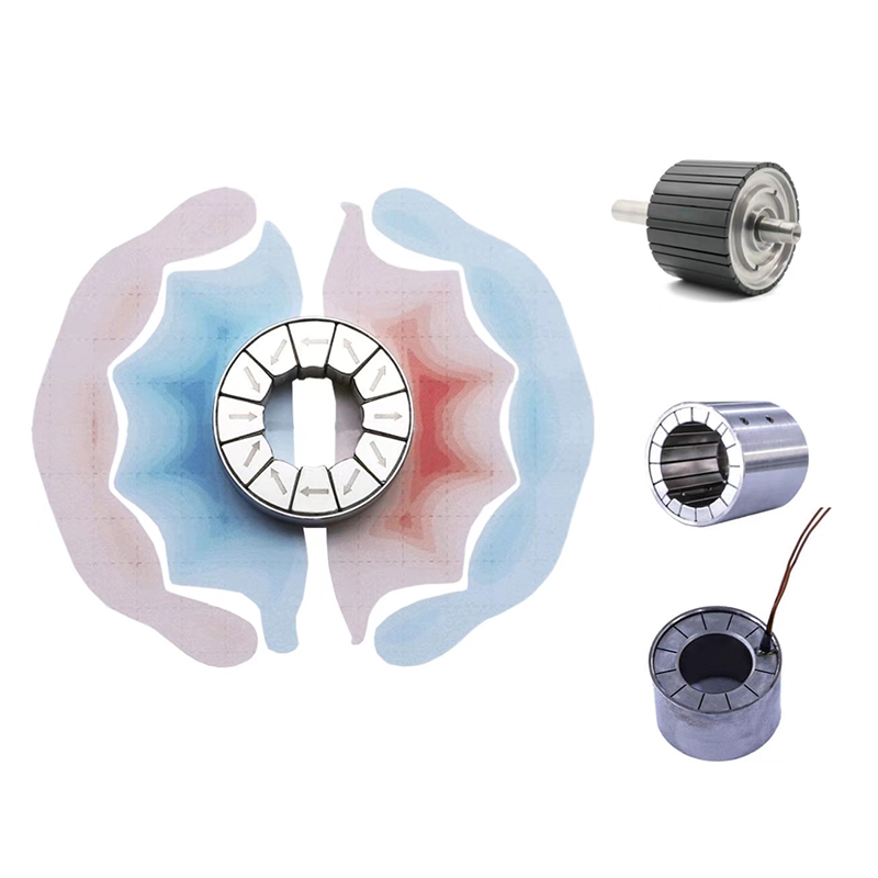 Custom Halbach Array Magnet Components for Motors and SensorsCustom Halbach magnet assemblies concentrate flux on one side and reduce back-side leakage, ideal for compact motors, sensors and precision magnetic systems.View Product →
Halbach Array versus a Conventional Magnet Array
Choose a Halbach array when flux per unit of mass on one face matters more than cost per kilogram; choose a conventional parallel array when part count, assembly time and unit cost decide the project. The comparison below assumes the same grade and the same overall envelope, which is the only fair way to judge the trade-off.
| Property | Conventional parallel array | Halbach array |
|---|---|---|
| Flux on the working face | Moderate and uniform | Concentrated, higher per unit volume |
| Flux on the back face | Similar to the working face | Close to zero |
| Back iron | Normally required | Often unnecessary or very thin |
| Pieces per pole | One or a few | Four to twelve or more |
| Orientation tolerance | Loose | Typically plus or minus 3 degrees, or tighter |
| Assembly cost | Low | High, driven by fixturing and handling |
| Typical duty | Holding, blocking, simple rotors | Motors, couplings, magnetic bearings, sensors |
Design Parameters That Decide Performance
Five parameters decide whether a Halbach array performs as intended: segments per pole, magnetization angle tolerance, grade and temperature class, mechanical retention, and surface protection.
- Segments per pole. Match the count to the application rather than to what a supplier can produce. Eight per pole is a sound default for motors; four is often enough for a coupling.
- Angle tolerance. Errors do not average out. In a Halbach pattern they partly cancel the reinforcement the layout depends on, so a stack with sloppy angles can end up weaker than a simple block array of the same mass.
- Grade and temperature class. N42 and N45 are common starting points, with H, SH or UH grades as operating temperature rises. Evaluate flux at the hottest point the magnet will see, not at room temperature; the published demagnetization curves are the correct reference.
- Retention. Sintered NdFeB is brittle and the array is a set of individually oriented pieces, so pockets, epoxy, retaining sleeves or a combination are needed to survive shock and thermal cycling.
- Surface protection. Nickel-copper-nickel, zinc, epoxy and phosphate coatings behave differently in salt spray and in bonded joints, a detail that matters more than usual when several magnet faces stay exposed to the surrounding structure.
Where Halbach Arrays Are Used
Halbach arrays are chosen where one-sided flux, low rotor mass or a smooth field is worth the added assembly cost — most often in motors, couplings, bearings and sensors.
- Brushless and slotless motors. One-sided flux allows a thinner rotor wall and a larger effective air gap, which reduces cogging and improves efficiency. The material is the same as in any other NdFeB motor magnet application; only the orientation changes.
- Magnetic couplings and gears. Two facing Halbach rings transmit torque through a barrier with no shaft seal.
- Magnetic bearings and levitation. The cancelled back face keeps stray flux away from adjacent structure and sensors.
- Position sensors and instrumentation. A sinusoidal magnetization pattern gives a clean, repeatable signal for encoders and resolvers.
- Medical and aerospace actuators. Where mass and envelope are tightly constrained, the weight saved by dropping back iron can justify the assembly cost.
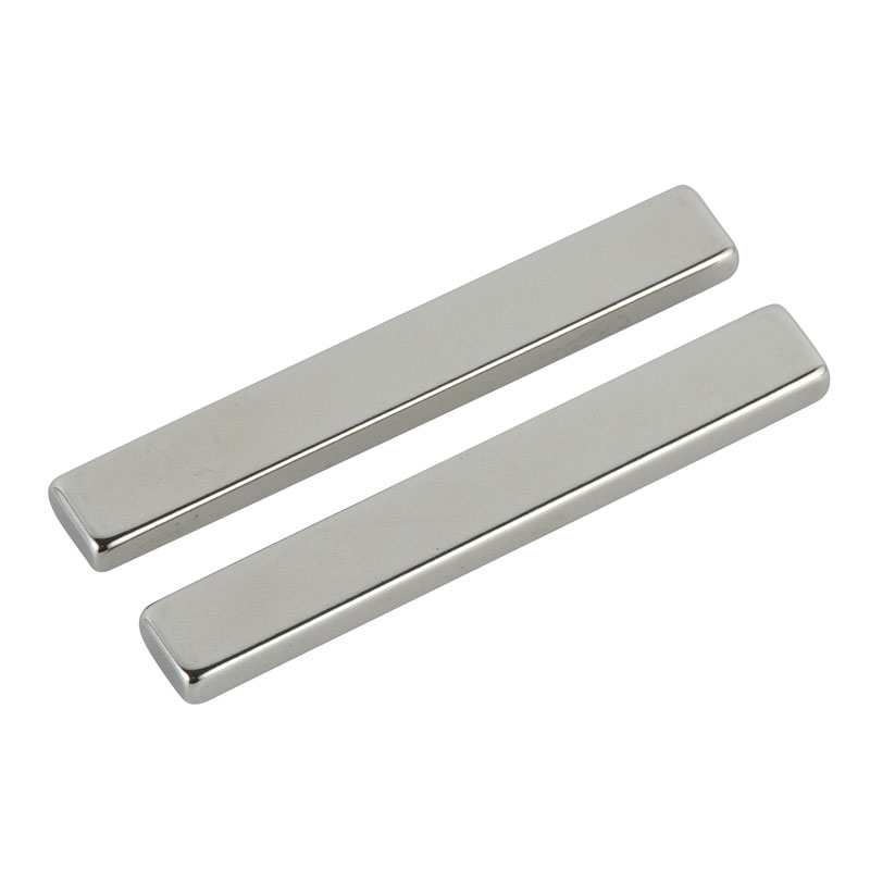 Sintered NdFeB Motor Magnets for Synchronous Motor ApplicationsCategory of custom sintered NdFeB magnets for synchronous motors, offering high magnetic strength, coercivity and stability for traction, industrial and renewable applications.View Product →
Tolerances, Assembly and Procurement Risks
The failure that catches most first-time buyers is not the magnet grade; it is angular error, glue-line variation and handling damage, all of which appear only after the assembly is bonded and measured.
- Angle error accumulates. A two-degree error on each of eight segments per pole can shift the field pattern enough to reduce peak flux at the working face.
- Glue lines consume space. Bonded segments reduce active magnet volume, so calculated performance must allow for adhesive thickness.
- Handling is a real hazard. A partly assembled array is strongly attracted to any steel surface and can pinch fingers or shatter segments.
- Verify after bonding. A gauss reading on the working face is the fastest check that orientation survived assembly, and a dimensional check on the outer radius confirms the assembly will still fit its sleeve.
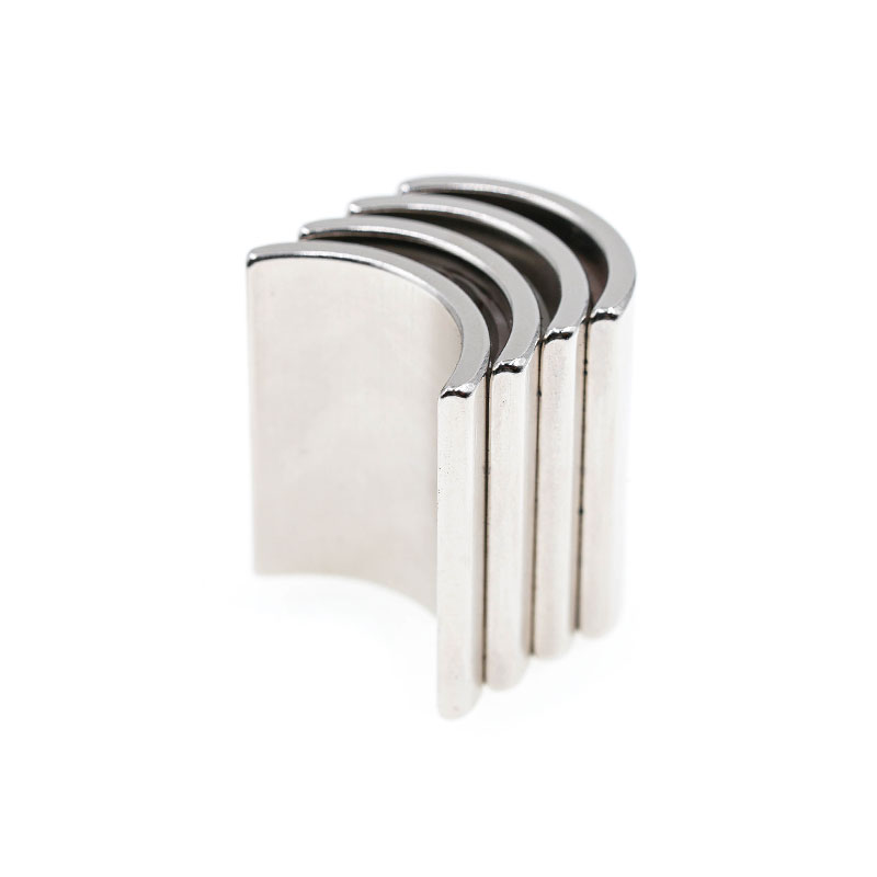 Custom Arc Permanent Magnets for Motor RotorsCurved arc magnets match rotor geometry to distribute flux evenly, reduce torque ripple and support synchronous, BLDC, servo and EV drive motors.View Product →
How to Specify a Halbach Assembly
To specify a Halbach assembly, describe the field you need and the environment it will live in, then let the supplier propose the geometry, grade and segment count.
- Working-face flux or air-gap field target, with the measurement point defined.
- Air gap and surrounding structure: steel, aluminium or composite.
- Maximum outer diameter, axial length and rotor mass limit.
- Operating temperature range, including worst-case stall conditions.
- Exposure to humidity, salt, oil, coolant or vacuum.
- Expected annual volume and preferred assembly method.
A manufacturer with in-house orientation and magnetization capability can usually answer with a segment count and a grade recommendation in a single round, which costs far less than discovering the answer on a rejected prototype.
Frequently Asked Questions
Is a Halbach array stronger than a normal magnet?
It is stronger on one face and almost neutral on the other. Against the same volume of conventionally magnetized material, the working face carries more flux — but only if every segment is oriented accurately.
How many magnets does a Halbach array need?
Four segments per pole is the minimum useful pattern. Eight per pole is the common choice for motors, and twelve or more where a smooth sinusoidal field is required. Multiply by the number of poles for the total piece count.
Can it be built from standard NdFeB blocks?
Yes. Standard rectangular and arc segments are used routinely. The array is defined by magnetization direction, not by shape; arc segments reduce glue joints in a cylindrical rotor, while blocks are cheaper and easier to source.
Does a Halbach array need back iron?
Usually not, or only a thin retaining sleeve. Because the back face is nearly cancelled, there is little flux to return through a yoke, and that is where most of the weight saving comes from.
Why does a Halbach assembly cost more?
More parts, tighter angular tolerances, dedicated magnetization fixtures and more assembly labour. Material cost may be similar; processing cost is not.
A Halbach array uses geometry to do work that a thicker magnet or a heavier yoke would otherwise have to do. Get the segment count, the angle tolerance and the temperature class right, and the result is a lighter, more efficient magnetic circuit. Get them wrong, and the assembly will look correct while quietly underperforming.