EN
 English
 中文简体
 русский
 Deutsch
 日本語
 한국어


Two identical N42 blocks can behave like two completely different magnets depending on which way you glue them together. Turn one of them 90 degrees and the flux that leaked off its back face disappears while the flux on the front face climbs. Repeat that rotation along a row, or around a ring, and you have built a Halbach array.
A Halbach array is a set of permanent magnets in which each magnet's magnetization direction is rotated by a fixed angle, usually 90 degrees, relative to its neighbour, so the field is concentrated on one side of the assembly and almost cancelled on the other. The payoff is practical: more usable flux in the air gap from the same magnet grade and volume, a lighter and thinner assembly because no steel return path is needed, and a smoother field that produces less cogging torque, less vibration and lower harmonic losses.
What Is a Halbach Array? A Working Definition
A Halbach array is a periodic magnet configuration in which the direction of magnetization rotates progressively along the array instead of pointing the same way in every piece.
The idea is named after Klaus Halbach, who developed it at Lawrence Berkeley National Laboratory from the 1970s onward for accelerator magnets such as undulators and wigglers, where a strong periodic field is wanted inside the beam gap and almost nothing outside it. The same requirement now drives motors, generators, magnetic bearings and magnetic couplings, and the geometry has not changed.
The 90-Degree Rotation Rule
The classic version uses four magnets per period, each rotated 90 degrees from the piece before it, so the magnetization direction completes one full turn every four magnets. On the working face the field vectors add together; on the back face they point against one another and cancel.
| Piece | Magnetization direction | Field on the working face | Field on the back face |
|---|---|---|---|
| 1 | 0 degrees (up) | Reinforces the gap field | Suppresses the stray field |
| 2 | 90 degrees (right) | Reinforces the gap field | Suppresses the stray field |
| 3 | 180 degrees (down) | Reinforces the gap field | Suppresses the stray field |
| 4 | 270 degrees (left) | Reinforces the gap field | Suppresses the stray field |
Why the Field Is One-Sided
The cancellation is vector addition, not luck. Every magnet pushes flux out of both faces, but rotating each piece by 90 degrees spreads those components across the array period, so they align on one face and oppose on the other. That is also why the field profile approaches a sine wave rather than the flat-topped pattern of a conventional block array. Increasing the count from four magnets per period to eight brings the waveform closer to a pure sine and lowers higher harmonics, at the cost of more pieces to place and orient accurately.
Why a Halbach Array Beats a Conventional Magnet Layout
For the same grade and the same magnet volume, a Halbach array delivers a higher flux density in the working gap and a far smaller stray field behind the assembly.
- Flux concentration. Useful field is pushed into the gap instead of being split between two faces.
- No back iron. Because the back face nearly self-cancels, the steel yoke that normally guides flux can be removed, cutting rotor mass and inertia.
- Smoother field. The near-sinusoidal distribution reduces torque ripple, cogging and acoustic noise in motor designs.
- The trade-offs. More pieces, tighter orientation tolerances, higher unit cost, strong assembly forces and a real demagnetization risk at the array edges.
Linear and Circular Halbach Arrays
The geometry usually follows the machine: a straight bar for linear motion, a ring for rotating machinery.
A circular array is assembled from arc segments set around a rotor or stator so that magnetization turns as you travel around the circumference. Arc segments behave differently from blocks during pressing, sintering, grinding and coating, and their radius, arc angle and circumferential pitch must match the pole geometry of the machine rather than a standard stock size.
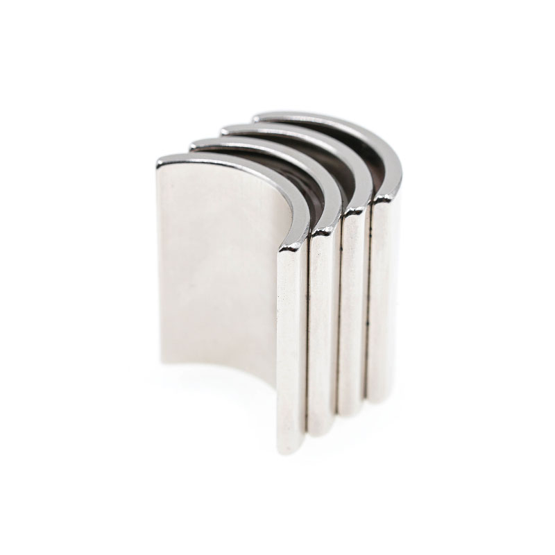 Arc Permanent Magnets for Motor Rotors and Rotating SystemsCurved permanent magnets matched to rotor or stator pole geometry for more uniform air-gap flux and reduced torque ripple in rotating machines.View Product →
| Design point | Linear Halbach array | Circular Halbach array |
|---|---|---|
| Magnet shape | Rectangular blocks, sometimes with skewed ends | Arc segments matched to the pole pitch |
| Field pattern | One-sided field along a straight track | Rotating field around the bore |
| Typical use | Ironless linear motors, maglev, magnetic springs | Slotless motors, generators, couplings, bearings |
| Watch-outs | Straightness and step alignment between blocks | Radius, arc angle and circumferential pitch tolerance |
Where Halbach Arrays Are Used
They are chosen wherever a strong, well-shaped field is needed on one face of an assembly while stray field, weight or iron content must stay low.
Motors and generators
Slotless and coreless brushless motors, axial-flux machines and ironless linear motors gain the most. With the array on the rotor, the designer can drop the iron return path, reduce rotor inertia and raise torque per kilogram.
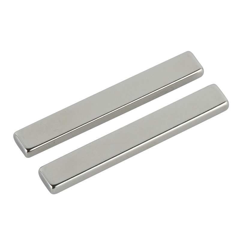 Sintered NdFeB Magnets for Synchronous Motors and GeneratorsHigh-energy motor magnets for synchronous motors, supporting compact one-sided magnetic circuits in slotless, axial-flux, linear, and direct-drive generator designs.View Product →
Wind power
Direct-drive permanent-magnet generators use the same one-sided principle to keep the magnetic circuit compact and the nacelle mass low. Sintered NdFeB magnets in wind turbine generators are specified with tight arc tolerances for exactly this reason.
Maglev, instruments and sensors
A linear array moving under a conductive plate induces lift without contact, the basis of several maglev demonstrators. Undulators and wigglers in synchrotron facilities rely on the same periodic one-sided field, while magnetic couplings, bearings and precision fixtures use smaller arrays to shape flux where it is needed and keep it away from nearby electronics.
Manufacturing Realities: Tolerances, Grades and Coatings
In a Halbach assembly, angular accuracy and piece-to-piece consistency matter more than the headline grade: a five-degree orientation error across one period visibly flattens the peak field and distorts the waveform.
- Angular tolerance. Specify magnetization angle to plus or minus two degrees or better, and agree how it will be measured, because visual inspection proves nothing.
- Grade and temperature. N35 to N52 covers most designs; for hot environments move to H, SH or UH grades and check the demagnetization curves at the real operating temperature, not at room temperature.
- Coating. Nickel-copper-nickel suits most motors; epoxy or zinc may be preferable where the coating must be thin or the environment is aggressive.
- Segmentation and assembly. Splitting large magnets into insulated pieces cuts eddy current losses but adds items to place, and the repulsive forces in a Halbach stack mean fixtures and cure schedules belong in the process plan.
- Verification. Batch testing with a Helmholtz coil or gauss meter mapping is the only reliable way to confirm that orientation and grade survived handling.
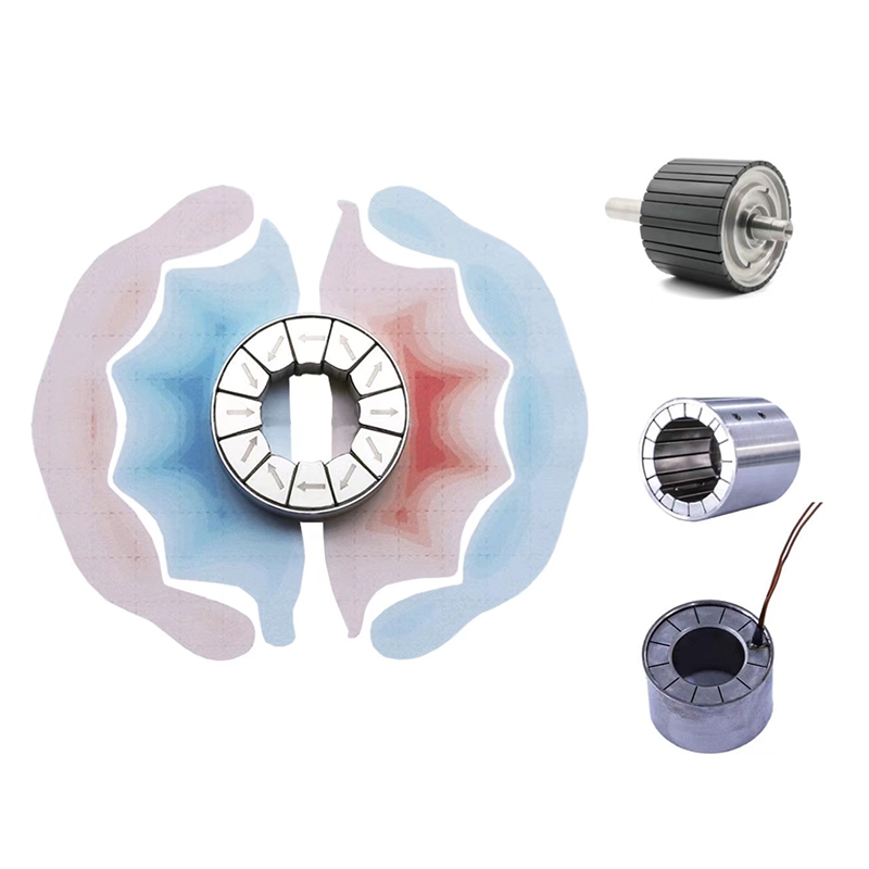 Custom Halbach Array Magnet Components for Precision Magnetic AssembliesCustomized Halbach assemblies using controlled magnetization directions to concentrate flux on one side for linear motors, PMSMs, and precision magnetic systems.View Product →
Specifying a Halbach Array: A Practical Checklist
Bring these points to the quotation stage and most of the surprises disappear before they reach the shop floor.
- State the working gap, the required flux density and whether peak or average field is the acceptance criterion.
- Define the geometry: pieces per period, linear or circular, inner or outer diameter.
- Fix grade, temperature class and coating for each piece rather than the assembly as a whole.
- Separate angular tolerance on magnetization from dimensional tolerance on mounting faces.
- Decide how the pieces are fixed: adhesive, sleeve, encapsulation or mechanical clamping.
- Agree on the inspection method and sampling rate before the first batch is produced.
Frequently Asked Questions
How many magnets does a Halbach array need?
Four magnets per period is the minimum for a meaningful one-sided field. Eight per period gives a smoother waveform and fewer harmonics, but doubles the number of pieces to orient and bond.
Can I build one from standard block magnets?
Yes, and it is a sensible way to prototype. Off-the-shelf blocks are fine for proving the concept, but volume production usually moves to custom arc or trapezoid pieces, because hand-assembled blocks rarely hold the angular tolerance the design assumes.
Does it make the field stronger than one large magnet?
It makes the field stronger on the working face and much weaker on the back face, using the same total magnet volume. The magnetic energy is unchanged; the array simply redirects it, which is exactly what a motor gap needs.
Is a Halbach array worth the extra cost?
When weight, gap flux or stray-field containment are the binding constraints, yes. When the design already has generous space and acceptable iron losses, a conventional layout with a steel yoke is usually cheaper to build and easier to qualify.
A Halbach array is not a new magnet; it is a smarter sequence of ordinary ones. Rotating each piece by 90 degrees concentrates flux on the working face, cancels it on the back face and removes the need for heavy return iron. The gains are real, but they are only as good as the angular tolerance, grade selection and assembly process behind them. Define the gap, the temperature class and the inspection method early, and the array you design on paper is the array you will get in production.