Sintered NdFeB Magnets for Synchronous Motor are high-performance permanent magnets specifically designed to meet the requirements of synchronous motor applications. These magnets are manufactured through a powder metallurgy sintering process that ensures high remanence, high coercivity, and excellent thermal stability, making them suitable for high-speed, high-efficiency, and high-torque motors. They are widely used in electric vehicles, industrial automation, wind power generators, robotics, and other precision motor systems.
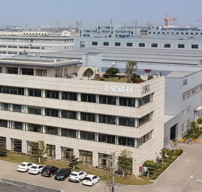
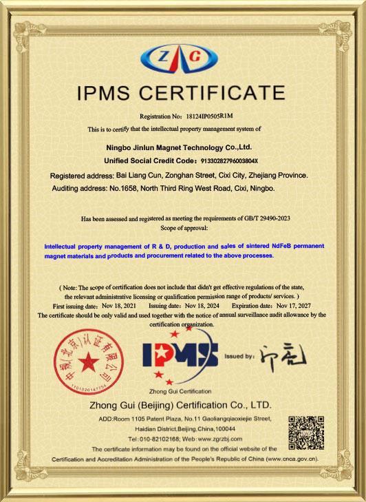
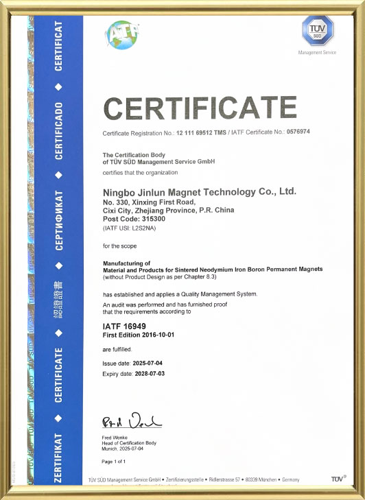
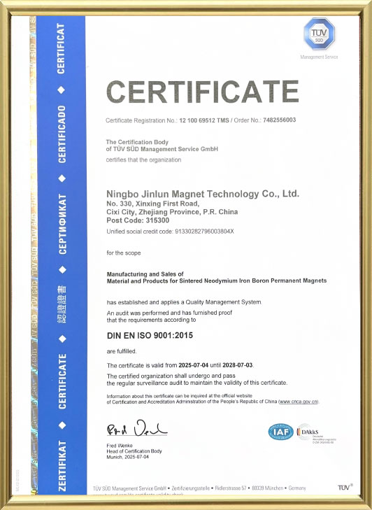
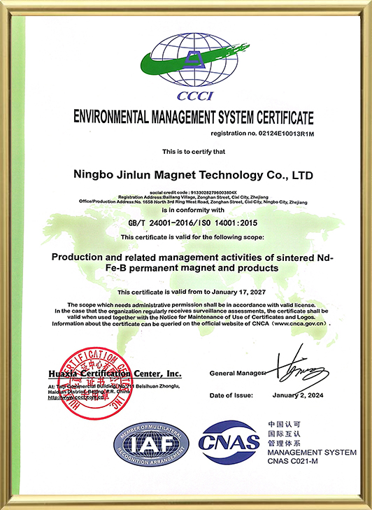
At Ningbo Jinlun Magnet Technology Co., Ltd., Sintered NdFeB Magnets for Synchronous Motor are produced using advanced international permanent magnet equipment and strict quality control processes. With over 30 years of experience, the company ensures the magnets meet industry standards for magnetic performance, dimensional accuracy, and reliability, providing solutions for both mass production and customized motor designs.
Core Functions and Features
Sintered NdFeB Magnets for Synchronous Motor share common characteristics that define their performance:
-
High Magnetic Energy Density: Strong remanence allows for compact motor designs while delivering high torque output.
-
High Coercivity: Resistance to demagnetization ensures stability under varying loads, high temperatures, and external magnetic fields.
-
Thermal Stability: Enhanced performance at elevated temperatures suitable for industrial and automotive motor applications.
-
Precision Manufacturing: Sintered process enables tight dimensional tolerances, essential for high-speed rotor assemblies.
-
Consistency and Reliability: Magnetic properties and mechanical integrity are consistent, supporting long-term operational stability.
These features make Sintered NdFeB Magnets suitable for synchronous motors that require efficient energy conversion and precise control.
Operating Principle in Synchronous Motors
Synchronous motors operate by maintaining a constant relationship between the rotor and the rotating magnetic field of the stator. Sintered NdFeB Magnets for Synchronous Motor are typically installed in the rotor to create a strong permanent magnetic field. The interaction between the rotor field and the stator’s AC field generates torque that drives the motor with high efficiency.
Key aspects include:
-
Rotor Placement: Magnets are embedded in the rotor core (surface-mounted or interior) according to motor design.
-
Flux Concentration: High remanence NdFeB magnets maximize flux density in the air gap, improving torque production.
-
Demagnetization Resistance: High coercivity prevents performance loss during transient currents or high-temperature operation.
This principle allows synchronous motors to maintain precise speed control, high power density, and efficient energy conversion.
Typical Applications and Examples
1. Electric Vehicle (EV) Traction Motors
Sintered NdFeB Magnets are widely used in traction motors for EVs due to their high torque density and efficiency.
Example: Permanent magnet synchronous motors (PMSM) in electric passenger vehicles and hybrid vehicles.
2. Industrial Automation Motors
Used in servo motors, spindle motors, and robotics for precise positioning and high-speed operation.
Example: High-speed pick-and-place robots, CNC machine tool spindles.
3. Renewable Energy Systems
Applied in wind turbine generators and hydroelectric synchronous generators to improve energy conversion efficiency.
Example: Small- and medium-scale wind turbine generators with high-performance NdFeB rotors.
4. Household and Commercial Appliances
Used in high-efficiency compressors, pumps, and fans requiring compact motor designs.
Example: Air-conditioning compressors and vacuum pump motors.
Comparison with Other Magnet Types
| Comparison Aspect | Sintered NdFeB Magnets | Ferrite / AlNiCo Magnets | Bonded NdFeB Magnets |
|---|---|---|---|
| Magnetic Strength | Very high | Low to moderate | Moderate |
| Coercivity / Demagnetization Resistance | High | Moderate | Low to moderate |
| Thermal Stability | Good (up to 200°C with grade selection) | Low | Low |
| Compactness | High (supports high power density) | Low | Moderate |
| Cost | Higher | Low | Moderate |
| Application Suitability | High-performance motors | General low-power devices | Cost-sensitive or shape-specific applications |
This comparison demonstrates why Sintered NdFeB Magnets are the preferred choice for high-efficiency synchronous motor applications.
Materials and Manufacturing Considerations
Sintered NdFeB Magnets for Synchronous Motor are produced using a powder metallurgy process:
-
Powder Preparation: High-purity Nd, Fe, B, and alloying elements are processed into fine powders.
-
Compaction: Powder is pressed into the desired magnet shape using a die.
-
Sintering: Magnets are sintered at high temperature to achieve dense, uniform microstructure.
-
Magnetization: Magnets are magnetized according to design specifications.
-
Surface Treatment: Coatings such as Ni-Cu-Ni or epoxy are applied to enhance corrosion resistance.
At Ningbo Jinlun Magnet Technology Co., Ltd., these processes are monitored with strict quality control to ensure consistency in magnetic performance and dimensional accuracy.
Maintenance and Usage Guidelines
While Sintered NdFeB Magnets are stable, proper handling ensures optimal performance:
-
Avoid mechanical shocks, dropping, or excessive vibration.
-
Do not expose to temperatures exceeding the magnet’s rated maximum.
-
Avoid strong external magnetic fields that may partially demagnetize the magnet.
-
Inspect rotor and motor assemblies regularly for proper fit and alignment.
-
Follow protective coating guidelines to prevent corrosion during operation.
Regular maintenance and careful installation support long-term stability and efficiency.
Frequently Asked Questions (FAQ)
Q1: Are Sintered NdFeB Magnets suitable for all synchronous motors?
A: They are ideal for high-performance, high-torque, and high-speed applications, but lower-demand motors may use alternative magnets such as ferrite.
Q2: Can the magnet size or grade be customized for specific motors?
A: Yes, magnet dimensions, shapes, and grades can be tailored according to motor design requirements.
Q3: What is the main advantage compared with bonded NdFeB or ferrite magnets?
A: Sintered NdFeB offers higher magnetic strength, higher coercivity, and better temperature performance, supporting more compact and efficient motor designs.
Conclusion
Sintered NdFeB Magnets for Synchronous Motor provide high-density, stable magnetic fields essential for modern high-efficiency and precision motor applications. Leveraging over 30 years of manufacturing experience and advanced equipment, Ningbo Jinlun Magnet Technology Co., Ltd. ensures reliable, high-performance magnets suitable for automotive, industrial, renewable energy, and precision motor applications worldwide.
 EN
EN English
 中文简体
中文简体 русский
 Deutsch
 日本語
日本語 한국어
한국어


