 EN
EN English
 中文简体
中文简体 русский
 Deutsch
 日本語
日本語 한국어
한국어
Industry News
Sep 19,2025
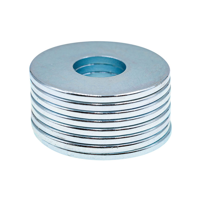
Ring Sintered NdFeB Magnets: A Comprehensive Practical Guide
1. Definition Analysis: Core Definition from Composition to Performance
Ring sintered NdFeB magnets are annular permanent magnets composed of neodymium (Nd), iron (Fe), and boron (B) as core components, supplemented by rare earth elements such as dysprosium (Dy), terbium (Tb), and niobium (Nb) to optimize performance, and manufactured through the "powder metallurgy sintering process". Their core characteristics can be defined from three aspects:
1.1 Composition and Functions
Role of Main Components: Neodymium (25%-35%) determines the upper limit of the energy product; if the neodymium content is less than 25%, the energy product will decrease by 10%-15%. Iron (60%-70%) forms the magnetic matrix; for every 0.1% decrease in iron purity, the magnetic permeability may drop by 2%. Boron (1%-2%) forms the Nd₂Fe₁₄B compound—the core crystal structure that generates strong magnetism. Insufficient boron content (less than 1%) will lead to incomplete crystal structure and significant attenuation of magnetic performance.
Regulatory Functions of Auxiliary Materials: For every 1% increase in dysprosium (Dy) content, the maximum operating temperature can be increased by 8-10°C, but the energy product will decrease by 3%-5%, requiring a balance between temperature resistance and magnetism. Niobium (Nb) content is controlled at 0.5%-1%, which can refine the grain size from 50μm to below 30μm, increasing the flexural strength of the magnet by 20%-30% and reducing the processing breakage rate.
1.2 Structural Advantages and Adaptability
Compared with square, cylindrical, and other shapes, the core advantages of the annular structure are:
Uniform Magnetic Field Distribution: The annular closed structure can control the magnetic flux leakage rate below 15%, while the flux leakage rate of square magnets of the same size is approximately 25%-30%. When radially magnetized, the magnetic field uniformity error in the inner hole of the ring is ≤3%, making it suitable for components requiring "surrounding magnetic fields" such as motor rotors and sensor coils, which can reduce magnetic field fluctuation noise during equipment operation.
Easy Installation: The central through-hole can be directly fixed with bolts or shaft sleeves without additional brackets. In UAV motors (with a weight requirement of ≤50g), it can save more than 30% of installation space. At the same time, the annular structure bears force more evenly, and its resistance to centrifugal force is 40% stronger than that of cylindrical magnets in high-speed rotation scenarios (such as 10,000rpm motors).
1.3 Core Performance Indicators (IEC 60404-8-1 Standard)
|
Performance Indicator |
Definition |
Typical Range |
Affected Scenarios |
Example of Deviation Impact |
|
Energy Product (BH)max |
Core indicator for measuring magnetic field strength |
28-52 MGOe |
Motor torque, sensor sensitivity |
When decreasing from 45MGOe to 40MGOe, motor torque drops by 12% |
|
Coercivity (HcB) |
Ability to resist demagnetization |
≥800-2000 kA/m |
Performance stability in high-temperature environments |
If HcB is less than 1000kA/m, the demagnetization rate exceeds 15% at 120°C |
|
Remanence (Br) |
Residual magnetic induction after magnetization |
1.15-1.45 T |
Equipment output power, magnetic field coverage |
A 0.1T decrease in Br shortens the sensor detection distance by 20% |
|
Maximum Operating Temperature |
Maximum temperature without irreversible demagnetization |
80-200°C (graded as N/M/H/SH/UH/EH) |
Environmental adaptability, equipment lifespan |
Exceeding the temperature by 10°C increases the annual demagnetization rate by 5%-8% |
|
Magnetic Permeability (μ) |
Indicator of magnetic field conduction capacity |
1.05-1.15 μ₀ (vacuum permeability) |
Magnetic field response speed |
A 0.05 decrease in μ increases sensor response delay by 10ms |
2. Core Advantages: Why They Are the First Choice in Multiple Industries
Among permanent magnetic materials such as ferrites and samarium-cobalt, ring sintered NdFeB magnets account for more than 30% of the market share, thanks to four irreplaceable advantages:
2.1 Leading Energy Product: Strong Magnetic Field in Small Size
Taking a new energy vehicle drive motor (requiring torque ≥300N·m) as an example, a ferrite magnet needs a diameter of 300mm and a thickness of 50mm to meet the demand, weighing approximately 3.5kg. In contrast, a ring magnet of N45 grade (energy product 43-46MGOe) with a diameter of 200mm and a thickness of 35mm can meet the standard, weighing only 1.2kg. This reduces the volume by 40% and the weight by 35%, directly reducing the motor load and increasing the vehicle's range by 15%-20% (calculated based on 15kWh power consumption per 100km; every 10kg weight reduction increases the range by 2-3km).
2.2 Customizable Temperature Stability
By adjusting the proportion of rare earth elements, temperature requirements of multiple scenarios can be met. The specific parameters and adaptation details of different grades are as follows:
Standard Grades (N/M): Grade N has a maximum operating temperature of 80°C, and Grade M of 100°C. They are suitable for wireless chargers (operating temperature 40-60°C) and small household appliances (such as fan motors, temperature ≤70°C). These scenarios have low temperature resistance requirements, and choosing standard grades can reduce costs by 20%-30%.
High-Temperature Grades (H/SH/UH): Grade H has a maximum operating temperature of 120°C, Grade SH of 150°C, and Grade UH of 180°C. Grade SH has a demagnetization rate of ≤3% when continuously operating at 150°C for 1000 hours, making it suitable for motor compartments of automobiles (temperature 120-140°C) and industrial oven sensors (temperature 150-160°C). Grade UH can meet the long-term use requirements of photovoltaic inverter motors (high-temperature environment 160-170°C).
Click to visit our products:Ring sintered NdFeB
Ultra-High-Temperature Grade (EH): With a maximum operating temperature of 200°C and a demagnetization rate of ≤5% at 200°C, it is used in special aerospace equipment (such as satellite attitude control motors). This scenario has extremely high requirements for performance stability. Although the price of Grade EH magnets is 80%-100% higher than that of Grade SH, it can prevent equipment failure in extreme environments.
2.3 Flexible Adaptability of Magnetization Directions
According to application scenarios, multiple magnetization directions can be designed to meet different magnetic field requirements. The specific adaptation details are as follows:
Axial Magnetization: The magnetic field is parallel to the annular axis, and the axial magnetic field strength can reach 80% of the surface magnetic field. It is suitable for headphone speakers (requiring axial magnetic fields to drive diaphragms) and small DC motors (such as toy motors with power ≤10W). This scenario has high requirements for the consistency of the magnetic field direction, and the deviation of axial magnetization must be controlled within ±5°.
Radial Magnetization: The magnetic field is along the radial direction of the ring, and the magnetic field uniformity error in the inner hole of the ring is ≤3%. It is the core choice for new energy vehicle drive motors (requiring radial magnetic fields to drive rotor rotation) and wind turbine rotors (with a diameter of 1-2m, requiring uniform radial magnetic fields). The magnetic energy utilization rate of radial magnetization is 15%-20% higher than that of axial magnetization.
Multi-Pole Magnetization: 8-32 poles are formed on the surface; the more poles, the smaller the magnetic field fluctuation. A ring magnet with 24-pole magnetization has a magnetic field fluctuation error of ≤1%. It is used in high-precision servo motors (such as CNC machine tool servo motors with positioning accuracy ±0.001mm), which can improve the stability of motor speed and reduce the speed fluctuation from ±5rpm to ±1rpm.
2.4 Significant Cost-Effectiveness Advantage
The following table compares the performance and cost of different permanent magnetic materials:
|
Type of Permanent Magnetic Material |
Energy Product Range (MGOe) |
Maximum Operating Temperature (°C) |
Price (RMB/kg) |
Suitable Scenarios |
Cost Advantage (vs. Samarium-Cobalt) |
|
Sintered NdFeB (N45) |
43-46 |
80 |
300-400 |
Consumer electronics, general motors |
70%-80% |
|
Sintered NdFeB (SH45) |
40-43 |
150 |
500-600 |
Automotive motors, industrial equipment |
60%-70% |
|
Samarium-Cobalt Magnet (SmCo2:17) |
25-30 |
250 |
1500-1800 |
Ultra-high temperature scenarios (e.g., aerospace) |
- |
|
Ferrite Magnet |
3-5 |
120 |
20-30 |
Low-cost scenarios (e.g., refrigerator door seals) |
However, insufficient magnetic performance |
Taking the gradient coil of a medical MRI (requiring an energy product of 38-42MGOe and an operating temperature of 120°C) as an example, using N42H grade sintered NdFeB costs approximately RMB 50,000 for the magnets of a single device. If samarium-cobalt magnets of the same performance are used, the cost would be RMB 120,000-150,000. Sintered NdFeB can reduce the equipment cost by 60% while meeting the magnetic field uniformity requirement (error ≤0.1%).
3. Manufacturing Process: 10-Step Refined Control Process
Eighty percent of the performance differences of ring sintered NdFeB magnets stem from process control. The complete production process goes through 10 key steps, each with strict parameter standards, and deviations in key parameters directly affect the final performance:
3.1 Raw Material Pretreatment (Dual Control of Purity and Precision)
Purity Requirements: Neodymium ≥99.5% (if the oxygen content exceeds 0.05%, Nd₂O₃ impurity phases will form, reducing the energy product by 5%-8%), iron ≥99.8% (if the carbon content exceeds 0.03%, pores will appear after sintering, reducing mechanical strength by 10%), boron ≥99.9% (if the hydrogen content exceeds 0.01%, hydrogen embrittlement will occur, making the magnet prone to cracking). The total amount of impurities (oxygen, carbon, hydrogen) must be ≤0.1%.
Batching Precision: An automatic weighing system (accuracy 0.001g) is used, with a batching error of ≤0.01%. For example, the neodymium proportion of N45 grade must be controlled at 31.5%±0.2%. If the neodymium proportion is 0.2% lower, the energy product will decrease from 45MGOe to 42MGOe. Meanwhile, after batching, the mixture must be blended in a nitrogen atmosphere for 30-60 minutes to ensure uniform composition; insufficient blending time will lead to local composition deviations and performance fluctuations exceeding 5%.
3.2 Vacuum Melting (Key Link for Oxidation Prevention)
Equipment and Protection: A medium-frequency induction furnace with a temperature of 1000-1200°C is used. High-purity argon (purity ≥99.999%, dew point ≤-60°C) is introduced during the melting process, with a flow rate of 5-10L/min. Too low a flow rate will cause oxidation of the alloy, forming a 2-3μm oxide layer on the surface, which is difficult to remove during subsequent crushing. The melting time is 1-2 hours; excessive melting time will cause volatilization of rare earth elements (neodymium volatilization rate is 0.5% per hour), affecting the composition ratio.
Ingot Processing: The alloy ingot after melting must be crushed within 24 hours (when the temperature drops below 200°C). If left for more than 48 hours, coarse grains (size exceeding 100μm) will form inside the ingot, and the energy product will decrease by 10%-15% after subsequent sintering. A jaw crusher is used to crush the ingot into 5-10mm particles; particles that are too large (exceeding 10mm) will increase the difficulty of subsequent fine grinding, while particles that are too small (less than 5mm) are prone to oxidation.
3.3 Powder Preparation (Control of Particle Size and Morphology)
Crushing Process: First, a jaw crusher is used for coarse crushing to 5-10mm, and then an air classifier mill is used for fine grinding to 3-5μm (particle size error ≤0.5μm). For every 1μm deviation in particle size, the magnet density changes by 0.1g/cm³ (standard density 7.5-7.6g/cm³). The working pressure of the air classifier mill is controlled at 0.6-0.8MPa; too low pressure will lead to uneven particle size, while too high pressure will produce overly fine powder (less than 2μm), increasing the risk of sintering agglomeration.
Oxidation Prevention: The entire fine grinding process is carried out in an argon atmosphere (oxygen content ≤50ppm). After collection, the powder must be sealed and packaged immediately (vacuum degree ≤1×10⁻²Pa). If exposed to air for more than 30 minutes, the oxygen content of the powder will rise to more than 200ppm, and oxidative pores will appear inside the magnet after sintering, reducing the coercivity by 8%-10%.
3.4 Magnetic Field Forming (Orientation of Magnetic Domains)
Equipment and Parameters: A bidirectional pressing machine is used, with an axial pressure of 200-300MPa (for every 50MPa increase in pressure, the green density increases by 0.2g/cm³) and a radial magnetic field of 1.5-2.0T (for every 0.2T increase in magnetic field strength, the magnetic domain orientation degree increases by 5%), ensuring that the easy magnetization direction of the magnetic powder is aligned with the magnetic field direction. The orientation degree must be ≥90%; otherwise, the energy product will decrease by 15%-20%.
Mold Design: The mold is made of cemented carbide (with high wear resistance and a service life of more than 100,000 times). The positioning structure on the inner wall ensures that the roundness error of the annular green body is ≤0.1mm and the height error is ≤0.05mm. The mold temperature is controlled at 50-60°C; too low a temperature will cause the green body to crack easily, while too high a temperature will invalidate the lubricant and affect demolding.
3.5 Vacuum Sintering (Crystal Densification)
Sintering Curve: A three-stage heating process must be strictly followed: ① Low-temperature stage (200-400°C): Hold for 2 hours to remove the lubricant (such as zinc stearate) in the green body, with a heating rate of 5°C/min; excessive heating rate will cause the lubricant to volatilize too quickly, resulting in cracks in the green body. ② High-temperature stage (1050-1120°C): Hold for 4-6 hours to sinter the powder particles into a dense crystal; for every 1 hour reduction in holding time, the magnet density decreases by 0.1g/cm³. ③ Cooling stage: Cool to room temperature at a rate of 5°C/min; excessive cooling rate will generate internal stress and cause the magnet to break.
Vacuum Degree Requirement: The vacuum degree in the sintering furnace must be ≥1×10⁻³Pa. Insufficient vacuum degree (such as 1×10⁻²Pa) will cause oxidation on the magnet surface, forming a 1-2μm oxide layer that requires removal during subsequent processing, increasing material waste. Meanwhile, unstable vacuum levels can cause performance fluctuations of more than 5% across different batches of magnets.
3.6 Aging Treatment (Performance Optimization)
Primary Aging: Hold at 900°C for 2 hours to precipitate the Nd₂Fe₁₄B main phase. A temperature deviation of ±5°C will cause a 3%-5% change in the main phase content. After holding, cool to 600°C at a rate of 10°C/min to avoid internal stress from rapid temperature changes.
Secondary Aging: Hold at 500-600°C for 4 hours to precipitate rare earth-rich phases (e.g., Nd₃Fe₁₄B), which distribute around the main phase and improve coercivity. A temperature deviation of ±10°C will cause a 100-200kA/m change in coercivity. Holding for less than 3 hours results in insufficient coercivity improvement, while holding for more than 5 hours reduces the energy product by 2%-3%.
3.7 Machining (Precision Dimension Control)
Rough Machining: Use a diamond grinding wheel (120-150 mesh) to cut the sintered blank to near-finished dimensions (with a 0.1-0.2mm machining allowance). Control the cutting speed at 10-15mm/min; excessive speed causes the cutting surface temperature to rise above 100°C, leading to local demagnetization. A cutting depth deviation of 0.05mm results in insufficient allowance for subsequent finishing, affecting dimensional accuracy.
Finish Machining: Use a CNC grinding machine for inner hole, outer circle, and end face grinding with a diamond grinding wheel (200-300 mesh). Control the grinding feed rate at 5-10μm per pass to ensure dimensional accuracy: diameter tolerance ±0.02mm, roundness ≤0.005mm, and surface roughness Ra ≤0.8μm. After grinding, clean with ultrasonic waves (40kHz frequency, 10-15 minutes) using a neutral water-based cleaning agent (pH 7-8) to remove residual grinding debris, which could cause blistering in subsequent surface treatment. For high-precision servo motor magnets (e.g., 50mm diameter ring magnets), post-finishing inspection with a laser diameter gauge ensures outer diameter deviation ≤0.003mm, preventing uneven air gaps between the motor rotor and stator that cause operational noise.
3.8 Surface Treatment (Corrosion Protection)
Parameters and application scenarios of different surface treatment processes must be precisely matched, with specific details as follows:
Zinc Plating (Zn): Adopt acid zinc plating with a coating thickness of 5-10μm (local thickness deviation ≤1μm). Post-plating passivation uses a chromate solution (pH 2-3) to enhance corrosion resistance. Neutral salt spray testing (5% NaCl solution, 35°C) must last ≥48 hours without red rust. Suitable for dry environments (e.g., indoor motors, office equipment sensors) with low cost (approximately RMB 0.5 per piece), but service life is only 1-2 years in environments with humidity ≥80%.
Nickel-Copper-Nickel Plating (Ni-Cu-Ni): Adopt a three-layer electroplating process: bottom nickel (3-5μm) for improved adhesion, middle copper (8-10μm) for enhanced corrosion resistance, and top nickel (4-5μm) for increased surface hardness (hardness ≥HV300), with a total thickness of 15-20μm. Salt spray testing lasts ≥120 hours, suitable for humid environments (e.g., water pump motors, outdoor small equipment) with a service life of 3-5 years. Control the current density during electroplating (1-2A/dm² for bottom nickel, 2-3A/dm² for middle copper, 1-1.5A/dm² for top nickel); excessive current density causes rough coatings, affecting appearance and corrosion resistance.
Epoxy Coating: Adopt electrostatic spraying with a coating thickness of 20-30μm (uniformity deviation ≤2μm), curing at 120-150°C for 30-60 minutes. The cured coating has adhesion ≥5MPa (cross-cut test) and excellent acid-alkali resistance (no peeling or discoloration after 24-hour immersion in 5% H₂SO₄ or 5% NaOH solution). Suitable for medical equipment (e.g., MRI gradient coils) and marine environment equipment (e.g., marine motors), with salt spray testing lasting ≥200 hours and a service life of 5-8 years. However, the coating has a high-temperature limit (maximum operating temperature ≤150°C), beyond which softening and peeling occur.
3.9 Magnetization (Magnetism Imparting)
Equipment Selection: Choose specialized equipment based on magnetization direction: unipolar head magnetizers (magnetic field strength ≥2.5T) for axial magnetization, multi-pole annular magnetizing fixtures (magnetic field strength ≥3.0T) for radial magnetization, and custom multi-pole magnetizing coils (8-32 poles) with turns adjusted according to pole count (e.g., 16-pole coils have twice the turns of 8-pole coils).
Magnetization Parameters: The magnetization current must be 3-5 times the magnet's coercivity. For example, SH-grade magnets with HcB=1200kA/m require a magnetization current of 3600-6000kA/m to ensure saturated magnetization (unsaturation reduces the energy product by 10%-15%). Control the magnetization time at 0.1-0.5 seconds (pulse magnetization); excessive time causes coil heating, affecting equipment life. Meanwhile, precisely position the magnet at the center of the magnetizing fixture; a positioning deviation exceeding 0.5mm causes magnetic field direction offset, affecting application performance (e.g., magnetization deviation of motor rotors causes speed fluctuations).
Post-Magnetization Inspection: After magnetization, use a gaussmeter to measure the surface magnetic field strength at 5 evenly distributed points on the magnet (top, bottom, left, right of the outer circle, and center of the end face). The deviation must be ≤5%; otherwise, re-adjust magnetization parameters or positioning to ensure uniform magnetic fields.
3.10 Comprehensive Inspection (Performance and Quality Control)
Magnetic Performance Testing: Use a permanent magnet material tester (e.g., Model NIM-2000, accuracy ±0.5%) to test BHmax, HcB, Br, and other parameters using the demagnetization curve method. Randomly sample 3-5 pieces per batch; if one piece fails, double the sample size. If failures persist, the entire batch is rejected. Before testing, condition the magnet at 25°C±2°C for 2 hours (temperature deviations affect results: Br decreases by 0.1% per 1°C increase).
Dimensional and Appearance Inspection: Use a coordinate measuring machine (accuracy ±0.001mm) for dimensional inspection with a sampling rate ≥10%, including outer diameter, inner diameter, thickness, roundness, and coaxiality (coaxiality between inner hole and outer circle ≤0.01mm). Defective products are marked separately and prohibited from entering downstream processes. Use a vision inspection system (resolution ≥2 million pixels) for appearance inspection to identify surface scratches (qualified if depth ≤0.1mm and length ≤2mm), coating peeling (qualified if area ≤0.5mm²), and cracks (any visible crack is rejected). The appearance defect rate must be controlled below 0.3%.
Reliability Testing: Conduct quarterly reliability sampling, including high-temperature stability testing (holding at maximum operating temperature for 1000 hours, with magnetic performance attenuation ≤5% for qualification), low-temperature stability testing (holding at -40°C for 100 hours, with performance attenuation ≤2% for qualification), and vibration testing (10-2000Hz sweep vibration with 10g acceleration, with no cracks and performance attenuation ≤3% for qualification) to ensure long-term reliability.
4. Typical Application Scenarios: Core Adaptation Solutions for Six Industries
The application of ring sintered NdFeB magnets spans multiple fields. The following are detailed parameters and effects of adaptation solutions for each industry:
|
Application Scenario |
Core Performance Parameter Requirements |
Surface Treatment Method |
Key Effects |
|
New Energy Vehicle Drive Motor |
Energy product 45-48MGOe (N45-N48), 150°C (SH grade), radial magnetization (8-16 poles), outer diameter 180-250mm |
Nickel-Copper-Nickel Plating (15-20μm) |
Motor power 200kW, speed 18000rpm, energy conversion efficiency 97% |
|
Industrial Servo Motor |
Energy product 48-50MGOe (N48-N50), 180°C (UH grade), multi-pole magnetization (24-32 poles), roundness ≤0.003mm |
Epoxy Coating (20-30μm) |
Positioning accuracy ±0.001mm, suitable for CNC machine precision machining |
|
Wireless Charger |
Energy product 33-36MGOe (N35), 100°C (M grade), axial magnetization, outer diameter 20-30mm |
Zinc Plating (5-10μm) |
Charging efficiency 15W, alignment deviation ≤2mm |
|
Medical MRI Gradient Coil |
Energy product 38-42MGOe (N42), 120°C (H grade), axial magnetization, uniformity error ≤0.05% |
Acid-Alkali Resistant Epoxy Coating |
Imaging resolution 0.5mm, clearly showing small brain lesions |
|
Wind Turbine Rotor |
Energy product 38-40MGOe (N40), 150°C (SH grade), radial magnetization, outer diameter 1000-1500mm |
Nickel-Copper-Nickel + Epoxy Composite Coating |
Annual power generation increased by 10%, failure rate ≤0.5 times/year |
|
Inverter Air Conditioner Compressor |
Energy product 38-42MGOe (N42), 100°C (M grade), radial magnetization, inner diameter 30-40mm |
Zinc Plating (8-12μm) |
Energy consumption reduced by 30%, noise ≤40dB, cooling speed increased by 20% |
5. Selection Guide: Four-Step Precise Demand Matching
Inappropriate selection can lead to performance waste or equipment failure. The following is a scientific selection process:
5.1 Step 1: Clarify Core Parameter Requirements
Magnetic Parameter Determination: Calculate the required energy product based on equipment power and performance requirements. For example:
Small DC motors (power ≤100W, torque ≤1N·m): Energy product 28-36MGOe (N30-N35) to meet basic power needs at low cost.
Medium-sized drive motors (power 100W-10kW, torque 1-10N·m): Energy product 38-48MGOe (N40-N48) to balance performance and cost, suitable for industrial automation equipment.
Large high-power equipment (power ≥10kW, torque ≥10N·m): Energy product 50-52MGOe (N50-N52) to ensure high torque output, suitable for new energy vehicles, wind turbines, and other scenarios.
Dimensional Parameter Confirmation: Provide the outer diameter (D), inner diameter (d), thickness (H), and tolerance requirements of the ring magnet. Calculate the weight using the formula "Volume = π×(D²-d²)×H/4" and adjust dimensions based on equipment weight limits (e.g., UAV motor magnets require weight ≤50g). Meanwhile, specify geometric tolerances such as roundness (≤0.005mm for high precision, ≤0.01mm for standard precision) and coaxiality (≤0.01mm) to avoid affecting assembly and application.
Magnetization Direction Selection: Determine based on equipment magnetic field requirements: radial magnetization for motor rotors (requiring surrounding magnetic fields), axial magnetization for speakers and sensors (requiring unidirectional magnetic fields), and multi-pole magnetization for high-precision servo motors (requiring multi-pole magnetic fields), with pole count adjusted according to speed requirements (higher speed requires more poles, e.g., 16-24 poles for 10,000rpm motors).
5.2 Step 2: Evaluate Operating Environment Conditions
Temperature Environment: Measure the maximum temperature and temperature fluctuation range of the equipment's operating environment to select the corresponding grade:
Low-temperature environments (-40-0°C, e.g., cold chain equipment): Standard N/M grades are sufficient (maximum operating temperature 80-100°C, stable performance at low temperatures), with no need for high-temperature grades to reduce costs.
Normal-temperature environments (0-80°C, e.g., indoor motors, consumer electronics): N/M grades are adequate; for scenarios with short-term temperature fluctuations (e.g., poor heat dissipation in summer), select H grade (120°C) to reserve a safety margin.
High-temperature environments (80-150°C, e.g., automotive engine compartments, industrial ovens): SH grade (150°C) is the basic choice; for long-term operation near 150°C, select UH grade (180°C) to avoid thermal demagnetization.
Ultra-high-temperature environments (150-200°C, e.g., aerospace equipment): EH grade (200°C) is the only option to ensure stable performance in extreme temperatures.
Corrosion and Humidity Environment: Select surface treatment based on environmental corrosiveness:
Dry and clean environments (indoor office equipment, household appliances): Zinc plating is sufficient, with low cost and basic protection.
Humid environments (water pumps, air conditioners, outdoor equipment): Nickel-copper-nickel plating for stronger corrosion resistance, suitable for environments with humidity ≤90%.
Acid-alkali corrosive environments (medical equipment, chemical equipment, marine environments): Epoxy coating for acid-alkali and salt spray resistance, suitable for complex corrosive environments.
Vibration and Impact Environment: High-vibration scenarios (construction machinery, automotive chassis motors, vibration acceleration 5-10g) require magnets with higher mechanical strength, such as niobium-added magnets (flexural strength ≥200MPa, impact strength ≥5kJ/m²). Meanwhile, add elastic buffer pads (1-3mm thick silicone pads) during installation to reduce magnet damage from vibration; low-vibration scenarios (indoor motors, sensors, vibration acceleration ≤5g) can use magnets with standard mechanical strength.
5.3 Step 3: Balance Performance and Cost
Avoid Over-Selection: Select the appropriate grade based on actual needs without blindly pursuing high grades. For example, household fan motors (power 50W, torque 0.5N·m) only require N35 grade (energy product 33-36MGOe); selecting N52 grade (energy product 50-52MGOe) increases costs by 200% but improves performance (motor speed, wind force) by less than 5%, resulting in cost waste. Similarly, ordinary sensors (detection distance 5mm) meet standards with N30 grade (energy product 28-30MGOe), requiring no higher grades.
Bulk Procurement Cost Optimization: For procurement quantities ≥1000 pieces, negotiate customized component parameters with suppliers to reduce costs while meeting performance requirements. For example, an industrial equipment factory purchasing ring magnets for assembly line motors (requiring energy product 40-42MGOe, maximum operating temperature 120°C) reduced dysprosium content from 2% to 1.5%, ensuring HcB ≥1000kA/m while lowering procurement costs by 15% per kilogram and saving approximately RMB 80,000 in annual procurement costs. Meanwhile, bulk procurement can negotiate shorter delivery cycles (from the standard 15 days to 7-10 days) to avoid production delays due to stockouts.
Cost Adjustment via Dimensional Optimization: Optimize magnet dimensions to reduce costs without affecting equipment assembly. For example, reducing the thickness of a ring magnet from 5mm to 4.8mm (meeting the 0.2mm assembly gap requirement) reduces the weight per piece by 4%. With an annual procurement of 100,000 pieces, this reduces raw material consumption by approximately 200kg and annual costs by about RMB 60,000. Additionally, standard-sized magnets (e.g., 50mm, 60mm outer diameter) cost 10%-15% less to produce than non-standard sizes (e.g., 52.3mm outer diameter), as non-standard sizes require custom molds, increasing mold costs and reducing production efficiency.
5.4 Step 4: Verify Supplier Qualifications
System Certification Verification: Prioritize suppliers with ISO 9001 Quality Management System certification to ensure clear quality control processes (e.g., raw material inspection, in-process inspection, final product 100% inspection). For automotive applications (e.g., drive motors, steering system sensors), confirm suppliers have IATF 16949 Automotive Quality Management System certification,which imposes stricter requirements on product consistency and traceability (e.g., retaining raw material procurement records, production parameter records, and inspection reports for each batch for at least 3 years). For magnets used in medical equipment (e.g., diagnostic instruments, therapeutic devices), suppliers must hold ISO 13485 Medical Device Quality Management System certification to ensure compliance with healthcare industry hygiene and safety standards.
Testing Capability Evaluation: Require suppliers to provide a list of testing equipment and annual calibration reports. Core testing equipment (e.g., permanent magnet material testers, coordinate measuring machines) must be calibrated by nationally recognized metrology institutions , with calibration reports valid for ≤1 year. Additionally, suppliers must issue "factory inspection reports" for each batch, including key data such as magnetic properties (measured BHmax, HcB, Br values), dimensional deviations, surface treatment thickness, and salt spray test results. For high-demand scenarios (e.g., aerospace equipment), request third-party inspection reports (issued by laboratories with CNAS accreditation) to ensure the objectivity of test results.
Production Experience and Capacity Verification: Prioritize suppliers with ≥5 years of experience and an annual production capacity of ≥500 tons. Such enterprises typically have mature process control capabilities (e.g., precision control of powder particle size, stability of sintering temperature), reducing the risk of product performance deviations due to production fluctuations (e.g., energy product deviation ≤3% across batches). Meanwhile, understand the supplier’s customer base; if they have served clients in industries similar to yours (e.g., providing products for new energy vehicle motor manufacturers or medical equipment factories), they are more likely to understand industry needs and reduce communication costs. Additionally, confirm the supplier’s emergency production capacity (e.g., monthly production expansion capability for urgent orders) to avoid delivery delays due to insufficient capacity.
6. Usage Precautions: Lifecycle Risk Mitigation
Standardized operation is required for ring sintered NdFeB magnets during transportation, installation, use, maintenance, and disposal to avoid performance attenuation, safety accidents, or equipment failures. Specific requirements are as follows:
6.1 Transportation: Anti-Collision and Anti-Magnetic Interference
Packaging Protection: Adopt a multi-layer packaging structure of "foam cushioning + carton + wooden pallet". Each magnet is wrapped in an independent foam box (thickness ≥5mm), with a gap of ≤1mm inside the foam box to prevent friction between the magnet and foam due to transportation vibrations. When packaging multiple magnets, place magnetic isolation plates (e.g., 0.5mm-thick iron sheets) between adjacent magnets to prevent collisions caused by strong magnetic attraction (a single N45-grade magnet with an outer diameter of 200mm has an attraction force of over 500kg, and collisions can easily cause edge chipping). Wooden pallets must be moisture-proof (coated with waterproof paint) to prevent magnet rust caused by rainwater infiltration during transportation.
Transportation Environment Control: Transport vehicles must be equipped with temperature and humidity recorders to ensure the transportation temperature is ≤40°C and humidity is ≤60%. Avoid transportation in extreme conditions such as high-temperature exposure (e.g., vehicle interior temperatures exceeding 60°C in summer) or heavy rain. Meanwhile, avoid routes passing through strong magnetic field areas (e.g., near large substations or electromagnetic cranes). If passing through such areas is unavoidable, add a magnetic shield (e.g., permalloy plate with thickness ≥1mm) outside the packaging to reduce the impact of external magnetic fields on the magnets (external magnetic field strengths exceeding 0.5T may cause partial demagnetization of the magnets).
Loading and Unloading Norms: Use forklifts or cranes for loading and unloading (selected based on package weight; manual handling is allowed for single boxes weighing ≤50kg). Do not drag packages directly. When handling individual magnets, use specialized fixtures (e.g., brass fixtures with rubber anti-slip layers); do not touch the magnets directly with hands (especially large-sized magnets, which have strong attraction and can easily cause hand pinching). Maintain a distance of ≥10cm between the magnets and other metal components (e.g., forklift tines) during loading and unloading to avoid collisions caused by attraction.
6.2 Installation: Precise Positioning and Standardized Operation
Tool Selection and Use: Installation tools must be made of non-magnetic materials, such as brass wrenches (selected based on bolt specifications), plastic screwdrivers, and ceramic fixtures. Do not use carbon steel tools (e.g., ordinary wrenches, pliers), as carbon steel tools will be strongly attracted by the magnets. The sudden attraction may cause the tools to collide with the magnets (resulting in surface scratches or cracks), and iron filings on the tool surface will adhere to the magnets, forming "local magnetic short circuits" (leading to uneven magnetic field distribution, e.g., a 10% increase in motor torque fluctuations). If temporary fixation of the magnets is required during installation, use non-magnetic tape (e.g., polyimide tape); do not use transparent tape (which easily leaves adhesive residues, affecting subsequent coating quality).
Installation Gap and Coaxiality Control: Reserve installation gaps according to equipment design requirements. For example, the air gap between the motor rotor and stator is typically 0.2-0.5mm. Use feeler gauges (accuracy 0.01mm) to check the gap during installation, ensuring uniform gaps around the circumference (deviation ≤0.05mm). Excessively small gaps will cause "rubbing" (friction between the rotor and stator) during motor operation, leading to wear of the magnet surface coating and magnetic powder shedding. Excessively large gaps will increase the magnetic flux leakage rate (a 0.1mm increase in gap increases the leakage rate by 5%), resulting in reduced motor output power. Meanwhile, ensure the coaxiality between the magnet and the mounting shaft is ≤0.01mm, which can be detected using a dial indicator (accuracy 0.001mm). Excessive coaxiality deviation will cause unbalanced centrifugal force when the magnet rotates at high speeds, leading to equipment vibration (vibration acceleration exceeding 5g may cause magnet loosening).
Multi-Magnet Assembly Sequence and Protection: When multiple ring magnets need to be assembled coaxially (e.g., a motor rotor composed of 6 magnets), determine the assembly sequence based on the principle of "heteropolar attraction". First, fix the first magnet to the mounting base using positioning pins, then push the second magnet axially using a specialized fixture with magnetic isolation (e.g., a plastic push block). Avoid direct hand contact to prevent finger pinching between the two magnets. After installing each magnet, use a gaussmeter to detect the surface magnetic field strength to ensure the correct magnetic field direction (reversed installation will cause mutual cancellation of the overall magnetic circuit, preventing normal equipment operation). After completing all assemblies, install retaining rings (e.g., stainless steel rings with thickness ≥3mm) at both ends of the magnets to prevent axial movement of the magnets during equipment operation.
6.3 Usage: Real-Time Monitoring and Overload Prevention
Real-Time Temperature Monitoring: Install temperature sensors (e.g., PT100 platinum resistance sensors with accuracy ±0.1°C) near the magnets to monitor the operating temperature in real time. Temperature data must be connected to the equipment control system. When the temperature reaches 90% of the maximum operating temperature (e.g., set the alarm temperature to 135°C for SH-grade magnets with a maximum operating temperature of 150°C), trigger an alarm and reduce the equipment load (e.g., reduce the motor speed from 18,000rpm to 15,000rpm) to prevent irreversible demagnetization caused by continuous temperature rise. For small equipment where sensors cannot be installed (e.g., micro-sensors), regularly detect the magnet surface temperature using an infrared thermometer (accuracy ±1°C). The detection frequency is determined based on usage intensity (e.g., continuous operation equipment requires detection every 2 hours).
Load Control and Abnormal Handling: Set the upper limit of equipment load based on the rated performance parameters of the magnets; do not allow overload operation. For example, for an N45-grade ring magnet supporting an industrial motor (rated torque 10N·m), the equipment load must be controlled at ≤9N·m (reserving a 10% safety margin). Long-term overload operation at 11N·m will increase the copper loss and iron loss of the motor, further increasing the magnet temperature (an increase of 8-10°C for every 10% overload). At the same time, the magnets will bear greater electromagnetic force, which may cause micro-cracks inside (crack propagation will reduce the energy product by 10%-15%). When equipment abnormalities occur (e.g., sudden speed drop, increased noise), stop the machine immediately to check whether the magnets are demagnetized, loosened, or damaged to avoid expanding the fault.
Magnetic Interference Protection: Avoid placing the magnets near strong magnetic field sources (e.g., electromagnetic welding machines, large electromagnets), as strong magnetic fields may cause reverse magnetization of the magnets (demagnetization rate exceeding 30%). If the equipment needs to be used in an environment with electromagnetic interference (e.g., factory workshops with multiple frequency converters), perform magnetic shielding on the components where the magnets are located (e.g., install a shield made of permalloy with thickness ≥2mm). The grounding resistance of the shield must be ≤4Ω to effectively absorb external electromagnetic interference and prevent magnetic field fluctuations from affecting equipment accuracy (e.g., sensor detection error increasing from ±0.1mm to ±0.5mm).
6.4 Maintenance and Disposal: Regular Inspection and Environmental Protection
Regular Maintenance Plan: Develop quarterly and annual maintenance plans. Quarterly maintenance includes: cleaning the magnet surface (wiping with a lint-free cloth dipped in alcohol to remove dust and oil, preventing impurities from affecting magnetic field distribution), inspecting the surface coating (checking for peeling and rust; if small-area rust is found, gently polish with fine sandpaper (≥800 mesh) and apply anti-rust paint), and inspecting installation fasteners (e.g., checking whether bolts and retaining rings are loose; tighten them in a timely manner according to the designed torque requirements, such as 25N·m for M8 bolts). Annual maintenance includes: sampling and testing magnetic properties (sampling 5% of the equipment per batch, disassembling and testing the BHmax and Br parameters of the magnets; if the attenuation exceeds 5%, conduct a batch inspection) and replacing aging components (e.g., magnetic shields and buffer pads need to be replaced after 3 years of use).
Disposal Specifications: Waste ring sintered NdFeB magnets are hazardous waste containing rare earths and must be handled by enterprises with a "Hazardous Waste Operation Permit"; do not discard them randomly or mix them with domestic waste. Before disposal, demagnetize the magnets using specialized demagnetization equipment (applying a reverse magnetic field to reduce the magnetic properties to less than 1% of the original value) to avoid safety accidents caused by the strong attraction of waste magnets (e.g., collisions caused by attracting metal components during recycling). Magnets with recycling value (e.g., no cracks or rust, magnetic performance attenuation ≤10%) can be handed over to professional recycling enterprises to extract rare earth elements (e.g., neodymium, dysprosium), and the recovered rare earths can be reused in the production of new magnets to achieve resource recycling. Magnets with no recycling value must undergo harmless treatment (e.g., high-temperature oxidation, converting iron and rare earth elements into stable oxides in an environment of 800-1000°C). The treatment data must be recorded and archived (retention period ≥5 years) for inspection by environmental protection departments.
7. Frequently Asked Questions (FAQs)
During the selection, use, and maintenance of ring sintered NdFeB magnets, industry practitioners often encounter various practical questions. The following are 8 high-frequency questions and professional answers:
7.1 After using the magnet for a period of time, the magnetic field strength decreases. How to determine whether it is reversible or irreversible demagnetization?
This can be initially determined using the "temperature recovery method": Place the magnet in a normal temperature environment of 25°C±2°C for 24 hours, then use a gaussmeter to measure the surface magnetic field strength. If the strength recovers by more than 50% compared to before cooling and can be restored to more than 90% of the original performance after re-magnetization, it is reversible demagnetization (mostly caused by short-term overheating or weak external magnetic field interference). If there is no significant recovery in strength after standing at room temperature, or the performance after re-magnetization is still lower than 80% of the original value, it is irreversible demagnetization (mostly caused by long-term overheating, strong reverse magnetic fields, internal cracks, or rust). For example, an SH-grade magnet (maximum operating temperature 150°C) used in a motor has a 20% decrease in magnetic field strength after operating at 160°C for 2 hours. After standing at room temperature, the strength recovers by 12%, and after re-magnetization, it is restored to 95% of the original value, which is reversible demagnetization. If it operates at 180°C for 10 hours, the magnetic field strength decreases by 40%, with no recovery after standing at room temperature, and only 60% of the original value is restored after re-magnetization, which is irreversible demagnetization.
7.2 How to use a simple method to detect whether the magnetization direction of the ring magnet is correct?
The "compass positioning method" or "iron powder distribution method" can be used: ① Compass positioning method: Bring a compass close to the outer surface of the magnet and rotate the magnet slowly. If the compass needle is always consistent with the radial direction of the magnet (pointing to the N or S pole of the magnet), it is radially magnetized. If the needle is always consistent with the axial direction of the magnet (pointing to the end face of the magnet), it is axially magnetized. If the needle points in different directions at different positions (e.g., the needle deflects 90° for every 45° rotation), it is multi-pole magnetized, and the number of poles matches the number of needle deflections (e.g., 8 deflections per full rotation indicate 8-pole magnetization). ② Iron powder distribution method: Sprinkle fine iron powder (particle size 100-200 mesh) evenly on the magnet surface and tap the magnet gently. If the iron powder is arranged along the radial direction (forming radial lines from the inner hole to the outer circle), it is radially magnetized. If arranged along the axial direction (forming parallel lines from the upper end face to the lower end face), it is axially magnetized. For multi-pole magnetization, the iron powder will form dense small lines in different polar regions, and the direction of the lines changes with the polarity.
7.3 If the surface of the ring magnet has scratches or slight rust, will it affect the performance?
This needs to be judged based on the degree of damage and location: ① If the scratch depth is ≤1/3 of the coating thickness (e.g., a zinc coating thickness of 8μm, scratch depth ≤2.5μm) and it is located in a non-working area (e.g., the end face of the magnet, which does not participate in magnetic field output), simply polish it with fine sandpaper (≥800 mesh) to remove burrs and clean it with alcohol; the performance will not be affected. If the scratch is located in the working area (e.g., the outer surface opposite the motor stator), even if the depth is shallow, it may cause uneven magnetic field distribution (local magnetic field strength decreases by 5%-8%). Whether to replace it depends on the equipment's requirements for magnetic field uniformity (e.g., high-precision servo motors require replacement, while ordinary fan motors can continue to be used). ② If there is point-like rust on the surface (area ≤1mm²) that has not penetrated the substrate (no rust powder falls off when scraped with a blade), first polish off the rust with fine sandpaper, then apply a layer of anti-rust paint (e.g., epoxy anti-rust paint with thickness 5-10μm); it can continue to be used after drying. If the rust area exceeds 5% or flaky rust layers appear (substrate damage is visible after scraping), the local coercivity will decrease (HcB in the rusted area may decrease by 100-200kA/m), and long-term use may cause overall demagnetization; the magnet must be replaced.
7.4 Due to limited space in small equipment, can large-sized ring magnets be cut into smaller sizes for use?
Self-cutting is not recommended; customized processing by professional suppliers is required. Self-cutting has three major problems: ① Destroying the magnetic domain structure: The magnetic domains of sintered NdFeB are arranged in a 定向 manner. Cutting with ordinary tools (e.g., angle grinders, hacksaws) will cause severe vibration and high temperatures (local temperatures exceeding 200°C), leading to disordered magnetic domains. After cutting, the energy product may decrease by 20%-30%, and cannot be restored by re-magnetization. ② Increasing the risk of cracking: Magnets are relatively brittle (flexural strength approximately 150-200MPa), and uneven force during self-cutting can easily cause penetrating cracks (crack rate exceeding 50%). Cracked magnets may break during use, causing equipment failure. ③ Severe surface oxidation: The magnet substrate (containing 60%-70% iron) is exposed to air during cutting and is prone to rapid oxidation (red rust appears on the cutting surface within 2 hours), which cannot be completely repaired by subsequent surface treatment. Professional suppliers use the "pre-magnetization cutting" process, using diamond wire cutting machines (cutting temperature ≤50°C, vibration amplitude ≤5μm) to cut the magnet to the required size before magnetization. After cutting, surface treatment and magnetization are performed to ensure no impact on magnetic performance, with a cutting accuracy of up to ±0.01mm.
7.5 There are performance differences between batches of the same model of ring magnets purchased. How to resolve this?
First, work with the supplier to analyze the causes of the differences. Common solutions are as follows: ① Verify parameter consistency: Check the factory inspection report of each batch to confirm whether core parameters such as BHmax, HcB, and Br are within the agreed tolerance range (e.g., agreed energy product deviation of N45 grade ≤3%). If the tolerance is exceeded, request the supplier to return or replace the goods. If within the tolerance range but the equipment has extremely high requirements for performance consistency (e.g., motors with multi-magnet synchronous operation require batch energy product deviation ≤2%), negotiate with the supplier to narrow the production tolerance (e.g., by optimizing powder particle size control and sintering temperature stability). If necessary, increase the sampling ratio (from 10% to 20%) and screen products with more similar performance into groups (e.g., grouping magnets with energy product 44-45MGOe and 45-46MGOe separately) to avoid mixing magnets with different performance, which may cause unstable equipment operation. ② Trace the production process: Request the supplier to provide production records of the different batches (e.g., raw material ratio, sintering temperature curve, aging treatment parameters) to identify whether performance differences are caused by changes in raw material batches (e.g., fluctuations in rare earth element purity) or adjustments to process parameters (e.g., sintering temperature deviation exceeding 5°C). If the issue stems from the process, urge the supplier to adjust the process (e.g., replacing the raw material batch, calibrating the sintering furnace temperature sensor) and provide process verification reports for subsequent batches. ③ Establish inventory classification management: If batch differences cannot be completely eliminated, mark each batch of magnets separately upon warehousing, record key performance parameters, and use them in accordance with the principle of "same batch first" to avoid cross-batch mixing. Meanwhile, for products from different batches with similar performance, conduct "matching grouping" through magnetic performance testing (e.g., grouping magnets with HcB deviation ≤50kA/m) to minimize performance differences within each group and reduce impacts on equipment.
7.6 When using ring magnets in low-temperature environments (e.g., -40°C), is special treatment required?
No special treatment is required in low-temperature environments, but two points should be noted: ① Performance change characteristics: Within the temperature range of -40°C to room temperature, the magnetic performance of sintered NdFeB magnets slightly improves (e.g., for N35 grade magnets at -40°C, Br is 2%-3% higher and HcB is 5%-8% higher than at 25°C), with no demagnetization issues. They are therefore suitable for cold chain equipment (e.g., refrigerated truck motors) and outdoor low-temperature sensors. However, attention should be paid to the impact of low temperatures on the mechanical properties of the magnets—brittleness slightly increases at low temperatures (flexural strength decreases by 5%-10%). During installation, severe impacts (e.g., knocking, dropping) should be avoided, and flexible buffer pads (e.g., 1-2mm thick silicone pads) can be added between the magnet and the mounting base to reduce the risk of cracking due to low-temperature impact. ② Thermal expansion adaptation: If the magnet is assembled with other metal components (e.g., motor shafts, mostly made of 45# steel), the difference in their thermal expansion coefficients must be considered (sintered NdFeB has a thermal expansion coefficient of approximately 8×10⁻⁶/°C, while 45# steel has approximately 11×10⁻⁶/°C). In low-temperature environments, the two materials contract differently, which may increase the assembly gap (e.g., for a 200mm diameter magnet-shaft fit, the gap may increase by 0.05mm when cooling from 25°C to -40°C). If the equipment has strict gap requirements (e.g., precision servo motors requiring gap ≤0.1mm), a gap compensation amount can be reserved during the design phase (e.g., reducing the room-temperature assembly gap from 0.1mm to 0.05mm), or matching materials with more similar thermal expansion coefficients (e.g., titanium alloy shafts with a thermal expansion coefficient of approximately 9×10⁻⁶/°C) can be selected.
7.7 How to determine whether a ring magnet has reached a "saturated magnetization" state?
This can be determined using the "magnetic performance testing method" or the "equipment operation effect method": ① Magnetic performance testing method: Use a permanent magnet material tester to detect the demagnetization curve of the magnet. If the "inflection point" (i.e., the point corresponding to HcB) of the demagnetization curve is clear and BHmax reaches the standard value of the grade (e.g., BHmax ≥43MGOe for N45 grade), the magnet is considered saturated. If the demagnetization curve has no obvious inflection point or BHmax is more than 10% lower than the standard value (e.g., BHmax of N45 grade is only 38MGOe), it is unsaturated. Additionally, the remanence Br can be measured; if Br reaches more than 95% of the standard value of the grade (e.g., standard Br ≥1.35T for N45 grade, measured Br ≥1.28T), it can also be determined as saturated. ② Equipment operation effect method: Install the magnet in the equipment and compare the rated performance with the actual operating performance. If the actual output (e.g., motor torque, sensor detection distance) reaches more than 95% of the rated value and operates stably (no torque fluctuations or excessive detection errors), the magnetization is saturated. If the actual output is more than 10% lower than the rated value (e.g., the motor's rated torque is 10N·m, but the actual torque is only 8.5N·m) and other equipment component failures (e.g., coil damage, mechanical jamming) are ruled out, the magnet is likely unsaturated and needs to be re-magnetized (by applying a higher magnetization current, e.g., increasing from 4000kA/m to 5000kA/m).
7.8 What is the "magnetic aging" phenomenon of ring magnets? How to slow down the magnetic aging rate?
"Magnetic aging" refers to the gradual attenuation of magnetic performance of magnets during long-term use due to environmental factors (temperature, humidity, vibration), manifested as annual decreases in BHmax and Br and slight fluctuations in HcB, typically with an annual attenuation rate of 1%-3% (under normal usage conditions). Measures to slow down magnetic aging are as follows: ① Control operating temperature: Avoid long-term use in environments close to the maximum operating temperature (e.g., for SH-grade magnets with a maximum operating temperature of 150°C, it is recommended to control the temperature below 130°C). For every 10°C decrease in temperature, the magnetic aging rate can be reduced by 20%-30%. For high-temperature scenarios, optimize equipment heat dissipation (e.g., adding cooling fans, using thermal conductive silicone grease) to lower the magnet operating temperature. ② Strengthen anti-corrosion protection: Regularly inspect the magnet surface coating; if coating damage (e.g., scratches, peeling) is found, repair it promptly with epoxy paint (5-10μm thick) to prevent substrate oxidation. In humid environments, install moisture-proof covers (e.g., acrylic covers with desiccants) around the magnets to control the environmental humidity below 60%. ③ Reduce vibration and impact: For high-vibration equipment (e.g., construction machinery motors), in addition to adding buffer pads between the magnet and the mounting base, regularly inspect the installation fasteners (e.g., bolt torque) to prevent magnet loosening and additional vibration. Meanwhile, avoid frequent equipment start-stop cycles (frequent start-stops cause repeated magnetic field changes, accelerating magnetic domain disorder) and extend the single operation time (e.g., controlling the number of daily start-stops to ≤10).
8. Selection and Use of Magnetic Performance Testing Equipment: Ensuring Testing Accuracy
Magnetic performance testing is a key link in controlling the quality of ring sintered NdFeB magnets. Appropriate equipment must be selected based on the testing scenario (laboratory, on-site), and operating procedures must be standardized. Specific requirements are as follows:
8.1 Types of Core Testing Equipment and Adaptation Scenarios
|
Equipment Type |
Testing Parameters |
Accuracy Range |
Adaptation Scenarios |
Operating Points |
Maintenance Requirements |
|
Permanent Magnet Material Tester (e.g., Model NIM-2000) |
BHmax, HcB, Br, Demagnetization Curve |
±0.5% |
Laboratory Batch Comprehensive Testing |
① Condition samples at 25°C±2°C for 2 hours; ② Center the sample during clamping to avoid curve distortion; ③ Calibrate the equipment before testing (verify with standard samples, error ≤0.3%) |
① Clean the testing coil monthly to remove dust; ② Send for metrological calibration annually and retain the calibration report; ③ Avoid use in strong magnetic field environments (e.g., near electromagnets) |
|
Portable Gaussmeter (e.g., Model HT201) |
Surface Magnetic Field Strength (B) |
±1% |
On-site Installation and Maintenance Testing |
① Maintain a 1mm distance between the probe and the magnet surface (each 0.1mm change in distance increases error by 2%); ② Measure 3 times at the same testing point and take the average; ③ Avoid probe collisions with the magnet (to prevent sensor damage) |
① Check battery power before each use (low power causes accuracy degradation); ② Calibrate the probe every 6 months; ③ Store in a dry environment (humidity ≤60%) |
|
Fluxmeter (e.g., Model WT10A) |
Magnetic Flux (Φ) |
±0.3% |
Overall Magnetic Performance Testing of Small Magnets |
① Fully center the sample in the testing coil (deviation causes error >5%); ② Zero the equipment before testing (to eliminate environmental magnetic field interference); ③ Regularly check the coil for wire breakage (breakage causes no reading) |
① Avoid coil bending (to prevent winding damage); ② Calibrate the testing accuracy annually (verify with standard magnetic flux samples); ③ Power on monthly when not in use for a long time (to prevent coil moisture) |
|
3D Magnetic Field Measuring Instrument |
3D Spatial Magnetic Field Distribution, Uniformity |
±0.8% |
Magnetic Field Testing of High-Precision Equipment (e.g., MRI Gradient Coils) |
① Set the testing grid (e.g., 5mm×5mm) to cover the magnet working area; ② Conduct testing in a magnetically shielded room to avoid external magnetic field interference; ③ Analyze data with professional software (to calculate uniformity error) |
① Ensure the testing platform is level (tilt causes spatial position error); ② Calibrate the sensor every 3 months; ③ Update the software version annually (to optimize data processing algorithms) |
8.2 Testing Procedures and Data Processing Specifications
Laboratory Comprehensive Testing Procedure: ① Sample Preparation: Randomly select 3 samples from each batch, remove surface impurities (e.g., oil, iron filings), and measure dimensions with a caliper (to confirm compliance with testing sample requirements, e.g., diameter 50-100mm). ② Environment Conditioning: Place the samples and equipment in an environment with temperature 25°C±2°C and humidity ≤60% for 2 hours. ③ Equipment Calibration: Calibrate with standard samples of the corresponding grade (e.g., N45 standard sample with BHmax=45±0.5MGOe) to ensure the equipment error ≤0.5%. ④ Sample Testing: Fix the sample on the testing platform, start the equipment to test BHmax, HcB, and Br, and record the complete demagnetization curve. ⑤ Data Determination: Compare the test data with product standards (e.g., N45 grade requires BHmax≥43MGOe, HcB≥1100kA/m, Br≥1.35T). If all 3 samples are qualified, the batch is determined to be qualified; if 1 sample is unqualified, double the sample size for testing. If failures persist, the entire batch is rejected.
On-Site Rapid Testing Procedure: ① Tool Preparation: Carry a portable gaussmeter, caliper, and lint-free cloth. Calibrate the gaussmeter before testing (verify with a standard magnetic field source, e.g., 100mT standard magnetic field, error ≤1%). ② Sample Selection: Randomly select at least 3 installed or to-be-installed magnets at the installation site. ③ Surface Cleaning: Wipe the magnet surface with a lint-free cloth to remove dust and oil. ④ Magnetic Field Measurement: Attach the gaussmeter probe vertically to the outer surface of the magnet, select 4 evenly distributed testing points around the circumference (0°, 90°, 180°, 270°), and record the magnetic field strength at each point. ⑤ Data Analysis: Calculate the average value and deviation of the 4 points (deviation ≤5% is qualified). If the deviation is excessive, check whether the magnet is unevenly magnetized or improperly installed.
Data Processing and Archiving Requirements: ① Data Recording: Test data must include the testing date, equipment number, sample number, environmental temperature and humidity, and complete parameter values (e.g., BHmax=44.8MGOe, HcB=1150kA/m, Br=1.38T), with no alterations allowed. ② Report Generation: Formal test reports (including test results, determination conclusions, and calibration certificate numbers) must be issued for laboratory testing, while on-site testing requires filling out test records (signed by the tester for confirmation). ③ Archiving Period: Test reports and records must be archived for at least 3 years (5 years for the automotive and medical industries) to facilitate subsequent traceability (e.g., customer complaints, quality issue analysis).
8.3 Common Causes of Testing Errors and Troubleshooting Methods
Equipment Errors: If the deviation between test data and standard values exceeds 1%, it may be caused by uncalibrated equipment or aging components. Troubleshooting methods: ① Re-calibrate with standard samples; if the error still exceeds 1% after calibration, check whether the test coil is damaged (e.g., winding short circuit) and replace the coil if necessary. ② For equipment used for more than 5 years, contact the manufacturer for comprehensive maintenance (e.g., replacing sensors, upgrading motherboards).
Environmental Errors: External magnetic fields, temperature, and humidity fluctuations can affect test results. Troubleshooting methods: ① Measure the environmental magnetic field with a magnetic field detector before testing (must be ≤0.01T); if it exceeds the standard, add a magnetic shield (e.g., permalloy plate) around the equipment. ② Pause testing when temperature and humidity fluctuations exceed limits (e.g., temperature change >5°C/h) and resume after the environment stabilizes. ③ Avoid placing metal objects (e.g., tools, mobile phones) near the equipment to prevent magnetic field interference.
Operational Errors: Sample clamping deviation and improper probe positioning can cause data distortion. Troubleshooting methods: ① Use positioning fixtures to center the sample during clamping (deviation ≤0.5mm) and avoid touching the sample during testing. ② Ensure the gaussmeter probe is perpendicular to the magnet surface (tilt angle ≤5°) and keep the probe stable during measurement (avoid shaking). ③ Train new operators (only qualified operators can work independently) and standardize operating procedures.
As core magnetic components in the industrial field, the performance, manufacturing processes, selection, and usage management of ring sintered NdFeB magnets directly determine the operational efficiency and service life of equipment. This article covers key links throughout the entire lifecycle from definition analysis to testing implementation, with the core goal of providing "practical and operable" knowledge for practitioners—whether quickly matching application scenarios through parameter tables, solving practical problems via FAQs, or controlling quality through testing standards, the ultimate objective is to help users avoid risks, optimize costs, and improve equipment performance.
In practical applications, it is necessary to flexibly adjust solutions based on industry characteristics (e.g., the automotive industry focuses on high-temperature stability and batch consistency, while the medical industry emphasizes corrosion resistance and magnetic field uniformity). At the same time, strengthen technical communication with suppliers, shifting from "passive procurement" to "active collaboration" to jointly optimize product parameters and processes. Only in this way can the performance advantages of ring sintered NdFeB magnets be fully utilized, providing support for equipment innovation and industrial upgrading.
Jinlun Magnet specialized in the research and development, production, and sales of high-performance rare-earth permanent magnet materials.
Quick Links
Contact Info.
-
 Sales00@jlmagnet.com
-
 +86-574-6321 2222
-
 No. 330 Xinxing 1st Road, Xinxing Industrial Park, Zonghan Street, Cixi City, Zhejiang Province, China
Mobile QR Code
Copyright © Ningbo Jinlun Magnet Technology Co., Ltd. All Rights Reserved.
China sintered NdFeB magnet manufacturer wholesale sintered NdFeB magnet factory

TOP

